
Differential pressure switch

A differential pressure switch, switch contact technology, applied in electrical switches, electrical components, circuits, etc., can solve problems such as connection problems, functional failures, etc.

Active Publication Date: 2012-12-05
HUBA CONTROL
View PDF9 Cites 0 Cited by
  • Summary
  • Abstract
  • Description
  • Claims
  • Application Information

AI Technical Summary

Problems solved by technology

Furthermore, conventional differential pressure switches are assembled as complete building blocks in most cases
The connection of the connecting wires to the fully assembled differential pressure switch can be problematic here and cause malfunctions

Method used


Image

  • Differential pressure switch
  • Differential pressure switch
  • Differential pressure switch

Examples


Embodiment Construction

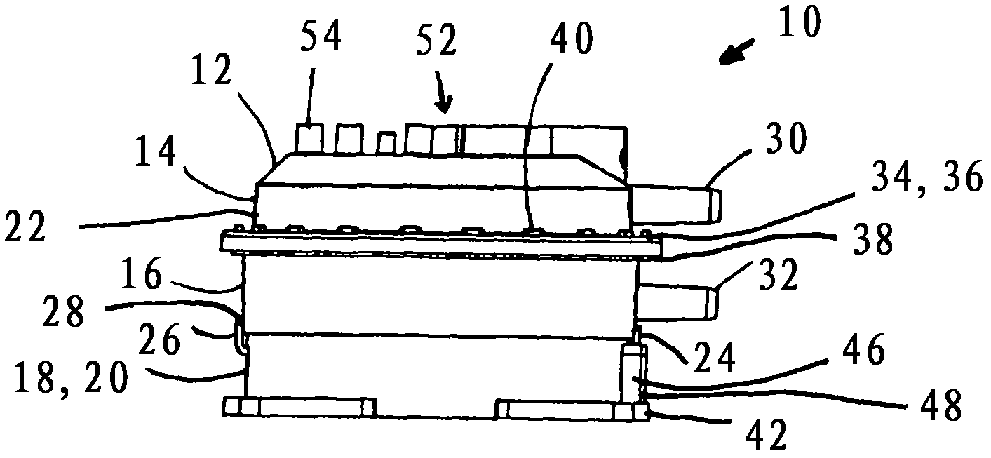
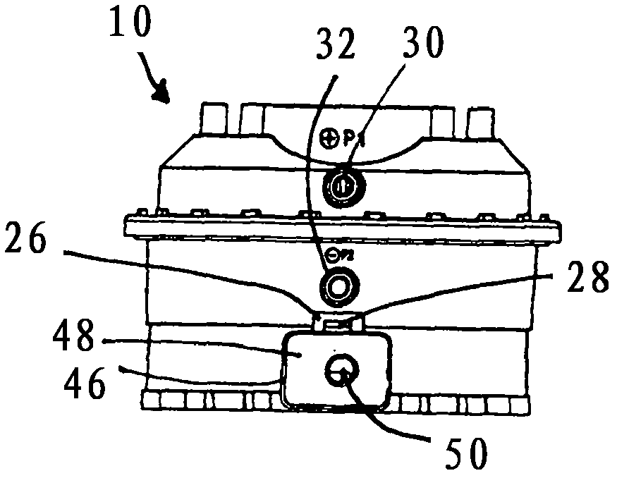
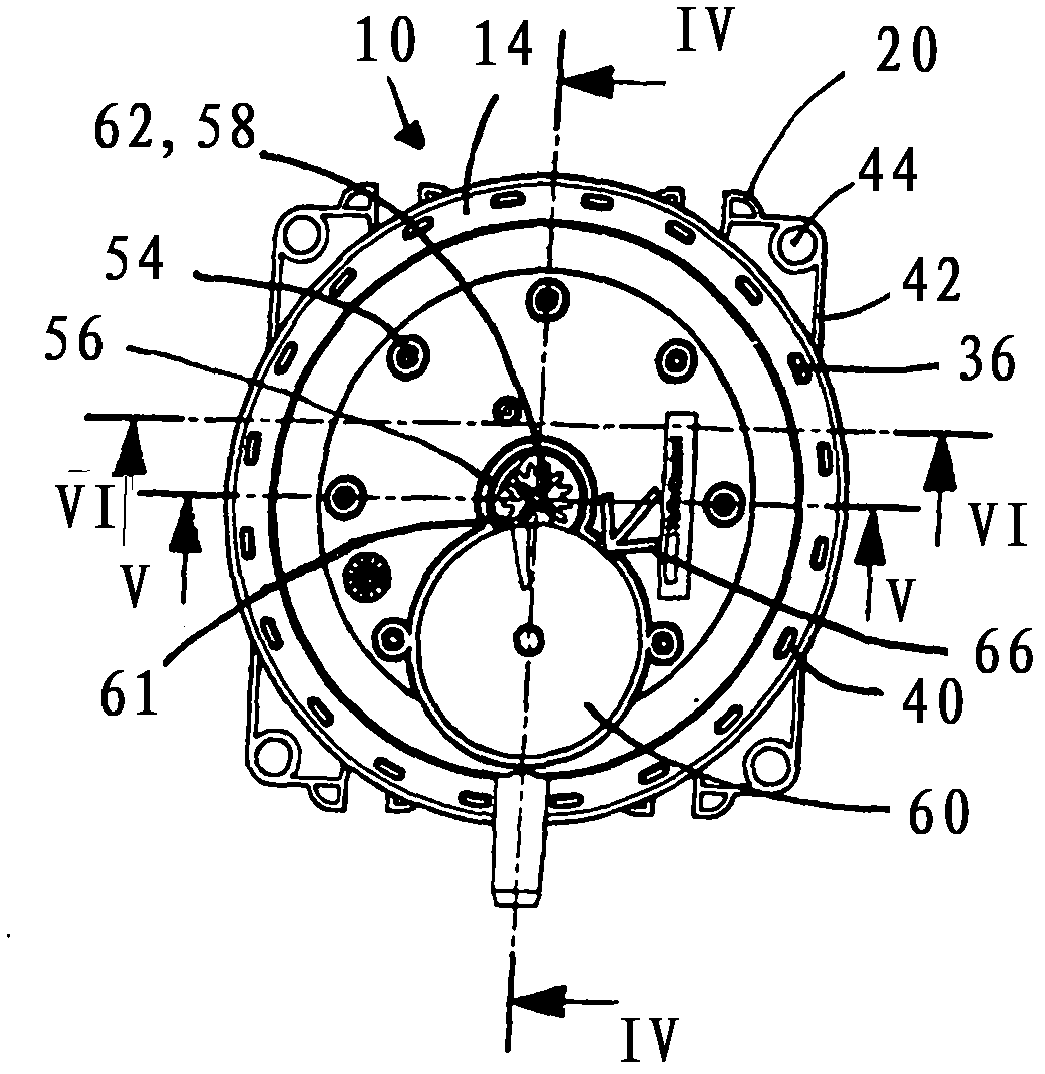
[0063] figure 1 A side view of a differential pressure switch 10 is shown. The housing 12 comprises a first housing part 14 , a second housing part 16 and a third housing part 18 which at the same time forms the base 20 . The first housing part 14 and the second housing part 16 together form a structural unit 22 which is attached to the third housing part 18 by means of a snap connection 24 . The first and second housing members 14, 16 jointly define an interior cavity 25 (see Figure 4 ). The snap-in connection 24 has two opposite jaws 26 which are formed on the third housing part 18 . These lugs 26 hook onto correspondingly shaped and provided projections 28 formed on the second housing part 16 . The snap-fit ​​connection 24 can be detached by pushing apart the clamping plates 26 in a direction away from the third housing part 18 .

[0064] The first housing part 14 has a first pressure connection 30 and the second housing part 16 has a second pressure connection 32 . ...


PUM


Abstract

The switch has housing (12) of which a first housing unit (14) and a second housing unit (16) form a structural unit (22), so that an interior space (25) is formed. An inner space is divided into pressure chambers (68,70) having respective pressure ports (30,32) by a diaphragm assembly (72). A switching contact piece (116) is connected with spring contact piece (113), such that the plug contacts (125) are engaged with the connection contact pieces (132), when the unit is placed on the third housing unit (18). A base forming third housing unit (18) is detachably mounted with structural unit and is connected with second housing unit to delimit a connection chamber (106). The diaphragm assembly and setting unit for adjusting the bias of spring (90) are provided on pressure chamber (68).

Description

technical field [0001] The invention relates to a differential pressure switch according to claim 1 . Background technique [0002] The differential pressure switch according to the invention is also used for determining relatively small differential pressures and subsequently triggering corresponding circuits. Filters and fans in the ventilation channels as well as flaps in the primary / secondary regulator can be monitored primarily with the differential pressure switch. It is also conceivable to use the differential pressure switch as overheating protection or for monitoring industrial air circuits. [0003] Conventional differential pressure switches have structurally insufficient switching accuracy or insufficient differential pressure sensitivity. This insufficient switching precision is caused by the suspension of the membrane on the housing and the associated insufficient frictionless movement of the membrane of the differential pressure switch. The diaphragms in co...

Claims


Application Information

Patent Timeline
Patent Type & Authority Applications(China)
IPC IPC(8): H01H35/34
CPCH01H35/34
Inventor A・马蒂斯
Owner HUBA CONTROL
Learn More