Leg positioning mechanism for orthopedist and use method of leg positioning mechanism
A technology of positioning mechanism and legs, applied in computer parts, biometric identification, passive exercise equipment, etc., to achieve the effect of increasing the angular range of motion
- Summary
- Abstract
- Description
- Claims
- Application Information
AI Technical Summary
Problems solved by technology
Method used
Image
Examples
Embodiment 1
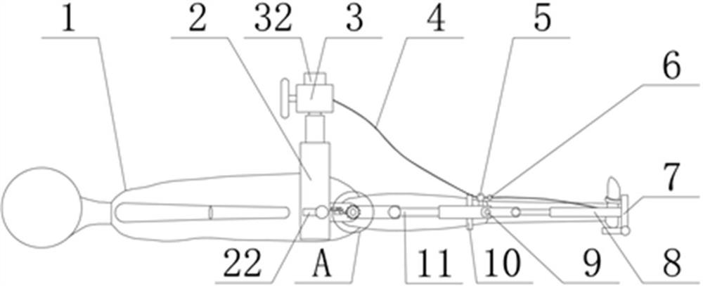
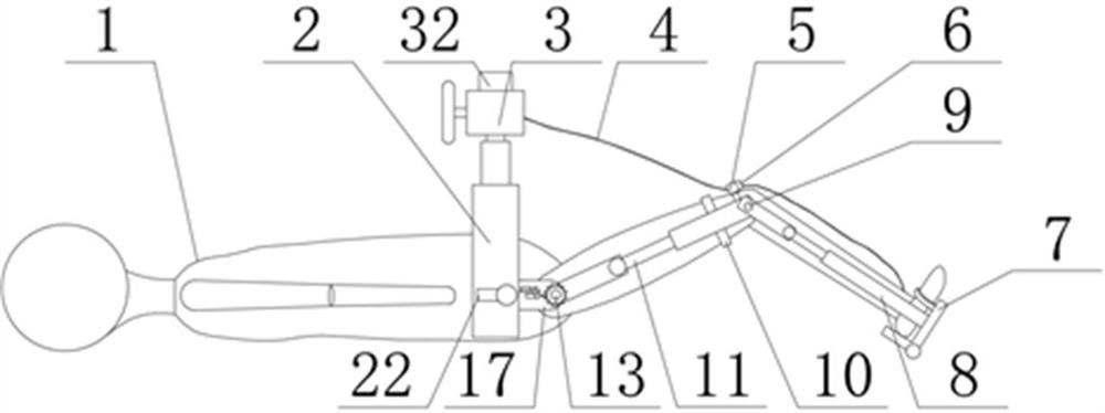
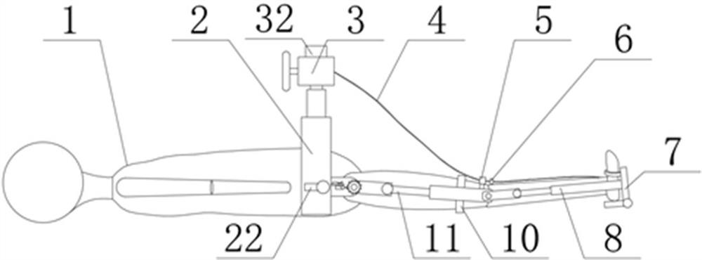
[0042] see Figure 1-10 , the present invention provides a technical solution:
[0043] A leg positioning mechanism for orthopedic surgeons, including a control module 32, the positioning mechanism includes a fixing module for supporting and fixing;
[0044] The fixing module includes two fixing frames 2 arranged on the front and rear sides. The two fixing frames 2 can move closer to the middle so as to fit and fix the hip bones on the left and right sides of the patient 1. The inner side of the fixing frame 2 is provided with an arc-shaped part 2b , the arc-shaped portion 2b can match the surface skin of the waist of the patient 1, increase the fitting effect between the fixed frame 2 and the patient, and play a role in increasing the fixing effect. The inner side of the fixed frame 2 is provided with an inclined portion 2a, and the inclined portion 2a Under the blocking effect of the hip bone, it can play a role of support and fixation, and further play a role in increasing...
Embodiment 2
[0049] see Figure 1-10 , the present invention provides a technical solution:
[0050] A leg positioning mechanism for orthopedic surgeons, including a control module 32, the positioning mechanism includes an identification module for training effect analysis and training speed analysis;
[0051] The training module includes a foot fixing module 7, a first turning point 9 and a second turning point 13. The bottom end of the foot fixing module 7 is provided with a roller, and the roller is used to reduce the resistance when the calf slides. The foot fixing module 7. After fixing the foot of the patient 1, the first connecting rod 8 can drive the lower leg to perform knee-bending activities, and the second rotation point 13 can be set at the hip joint, which can ensure the rotation of the second connecting rod 11. Move up and down, the first pivot point 9 can be set at the knee joint, and it can ensure the up and down movement of the first connecting rod 8. A first link is arr...
Embodiment 3
[0057] see Figure 1-10 , the present invention provides a technical solution:
[0058] In this embodiment, the same parts as those in Implementation 2 will not be repeated, and the difference lies in the following;
[0059] By adopting the above-mentioned technical solution: when the thigh is raised, the first drawstring 4 does not engage with the connecting block 6, and the engaging component 15 and the movable component 16 lock the second rotation point 13. At this time, the lifting angle of the thigh Being fixed, the patient 1 can freely realize the movement of the knee joint through the movement of the calf muscles, and realize the active training of the knee joint. At the same time, if the driving module 3 works, the pull rope 4 can pull the first connecting rod 11 Drive the calf to move up and down. In this environment, you can also perform forward deep knee movement to increase the angular range of motion of the calf and realize the second type of training;
PUM
 Abstract
Description
Claims
Application Information
 - R&D
- Intellectual Property
- Life Sciences
- Materials
- Tech Scout
- Unparalleled Data Quality
- Higher Quality Content
- 60% Fewer Hallucinations
Browse by: Latest US Patents, China's latest patents, Technical Efficacy Thesaurus, Application Domain, Technology Topic, Popular Technical Reports.
© 2025 PatSnap. All rights reserved.Legal|Privacy policy|Modern Slavery Act Transparency Statement|Sitemap|About US| Contact US: help@patsnap.com


