Environment-friendly efficient ceramic product production equipment and use method
A technology for production equipment and ceramics, which is applied in the field of environmental protection and high-efficiency ceramic product production equipment, which can solve the problems of long water absorption time, insufficient environmental protection, and low service life, and achieve the effects of high reuse rate, easy separation, and easy operation
- Summary
- Abstract
- Description
- Claims
- Application Information
AI Technical Summary
Problems solved by technology
Method used
Image

Examples
Embodiment 1
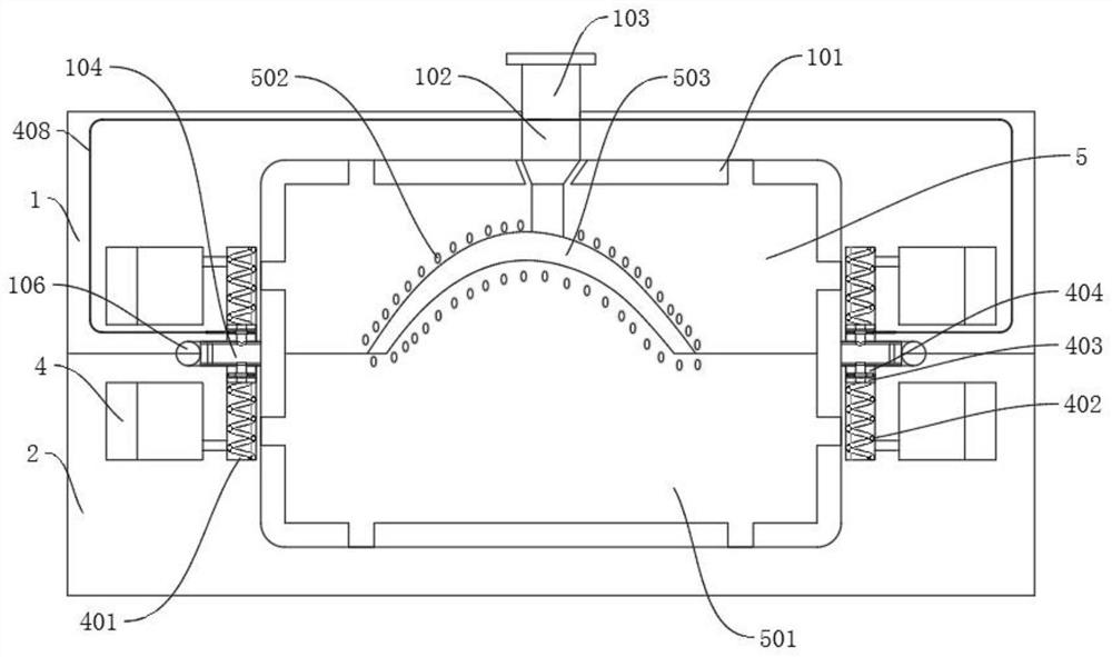
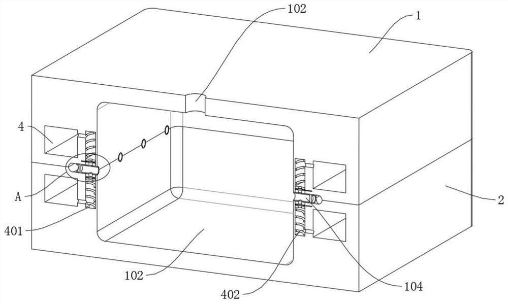
[0039] refer to Figure 1-8 , an environment-friendly and high-efficiency ceramic product production equipment, comprising a mold part composed of a slidable upper mold part 5 and a lower mold part 501, and a profiling mold cavity 503 is arranged between the upper mold part 5 and the lower mold part 501 , also includes: a connecting shell composed of an upper mold connecting frame 1 and a lower mold connecting frame 2 that can be slidably attached to each other, a cavity 101 is provided between the connecting shell and the mold parts, and the upper mold connecting frame 1 and the upper mold parts 5 are fixed Connected, the lower mold connecting frame 2 is fixedly connected with the lower mold part 501; wherein, the upper mold part 5 and the lower mold part 501 are water-permeable epoxy resin; the closure of the connection shell can improve the airtight effect through a counterweight or other heavy objects , a profiling cavity 101 is provided between the upper mold connecting f...
Embodiment 2
[0060] refer to Figure 1-8 , a method for using environment-friendly and efficient ceramic product production equipment, mainly comprising the following steps:
[0061] S1. Fit the upper mold connecting frame 1 and the lower mold connecting frame 2 of the preset cavity 101 to form a connecting shell, and inject ceramic product slurry into the cavity 101 through the grouting port 102;
[0062] S2, start the suction fan blade 301 driven by the driving motor, and pump air to the suction port 3 and the connecting pipe 106, so that the gas and moisture in the cavity 101 flow to the connecting pipe 106 and the suction port 3 through the semi-permeable membrane 105;
[0063] When the air suction fan blade 301 is driven and rotated by the motor, it is used to extract the gas in the air suction port 3 and guide the flow direction of the gas;
[0064] When the gas in the cavity 101 is initially pumped, since there is a lot of water in the ceramic slurry, if the extraction force is too...
Embodiment 3
[0073] refer to figure 1 , a method of using environment-friendly and high-efficiency ceramic product production equipment, which is basically the same as Embodiment 2, and furthermore, a mold pipe fitting 502 for connecting the cavity 101 and the mold cavity 503 can be set on the mold part, so that the mold cavity The effect of 503 inflation is good.
PUM
 Abstract
Description
Claims
Application Information
 - R&D Engineer
- R&D Manager
- IP Professional
- Industry Leading Data Capabilities
- Powerful AI technology
- Patent DNA Extraction
Browse by: Latest US Patents, China's latest patents, Technical Efficacy Thesaurus, Application Domain, Technology Topic.
© 2024 PatSnap. All rights reserved.Legal|Privacy policy|Modern Slavery Act Transparency Statement|Sitemap