
Vulcanizing equipment

A technology of equipment and vulcanization chamber, applied in the field of vulcanization equipment, can solve the problems of large space occupation, limitation of vulcanization tire processing specifications, unfavorable vulcanization bladder gas circulation, etc., achieve high heating efficiency and improve heat transfer efficiency

Pending Publication Date: 2022-03-15
HIMILE MECHANICAL SCI & TECH (SHANDONG) CO LTD
View PDF3 Cites 7 Cited by
  • Summary
  • Abstract
  • Description
  • Claims
  • Application Information

AI Technical Summary

Problems solved by technology

[0006] Therefore, the technical problem to be solved by the present invention is to overcome the defects in the prior art that the horizontally arranged equipment of the vulcanization bladders takes up too much space, limits the processing specifications of vulcanized tires, and is not conducive to the gas circulation in the vulcanization bladders

Method used


Image

  • Vulcanizing equipment
  • Vulcanizing equipment
  • Vulcanizing equipment

Examples


Embodiment 1

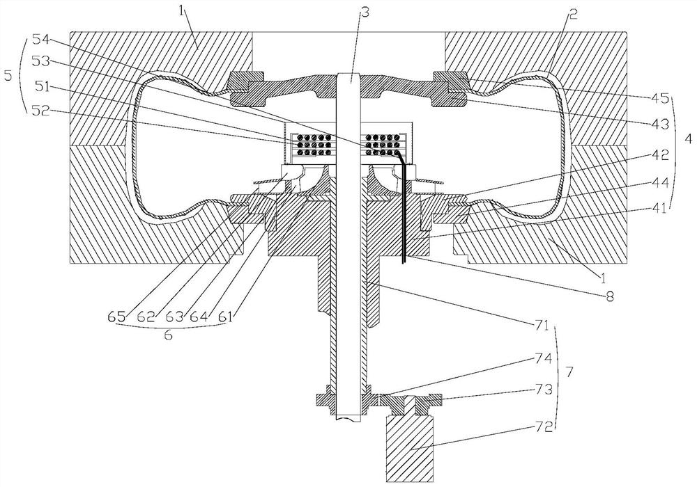
[0086] This embodiment provides a vulcanization equipment, such as Figure 1-Figure 9 As shown, in industrial production, vulcanization equipment is usually used to increase the overall hardness of certain materials. Taking tire vulcanization as an example, tire vulcanization refers to the vulcanization of the outer tire, which is vulcanized by means of model pressure. Before vulcanization, the tire is a plastic rubber with viscoelasticity, which is easy to deform, has low strength, and has no use value. Through vulcanization, the plastic rubber is cured and becomes a highly elastic rubber with useful value.

[0087] The prior art provides a tire vulcanization equipment, such as Figure 11 As shown, a heating component 5 is set in the vulcanization bladder 2 to directly heat the heating medium gas, and a gas circulation component 6 is set in the vulcanization bladder 2 to make the temperature distribution in the vulcanization bladder 2 uniform. However, in the solution provid...

Embodiment 2

[0135] This embodiment provides a vulcanization equipment, such as Figure 8 As shown, the difference from Embodiment 1 is that the heating assembly 5 and the gas circulation assembly 6 are kept in the vulcanization bladder 2 along the axial layer of the central rod 3, and the positions of the heating assembly 5 and the gas circulation assembly 6 are exchanged, so that the gas circulation assembly 6 is located above the heating assembly 5 .

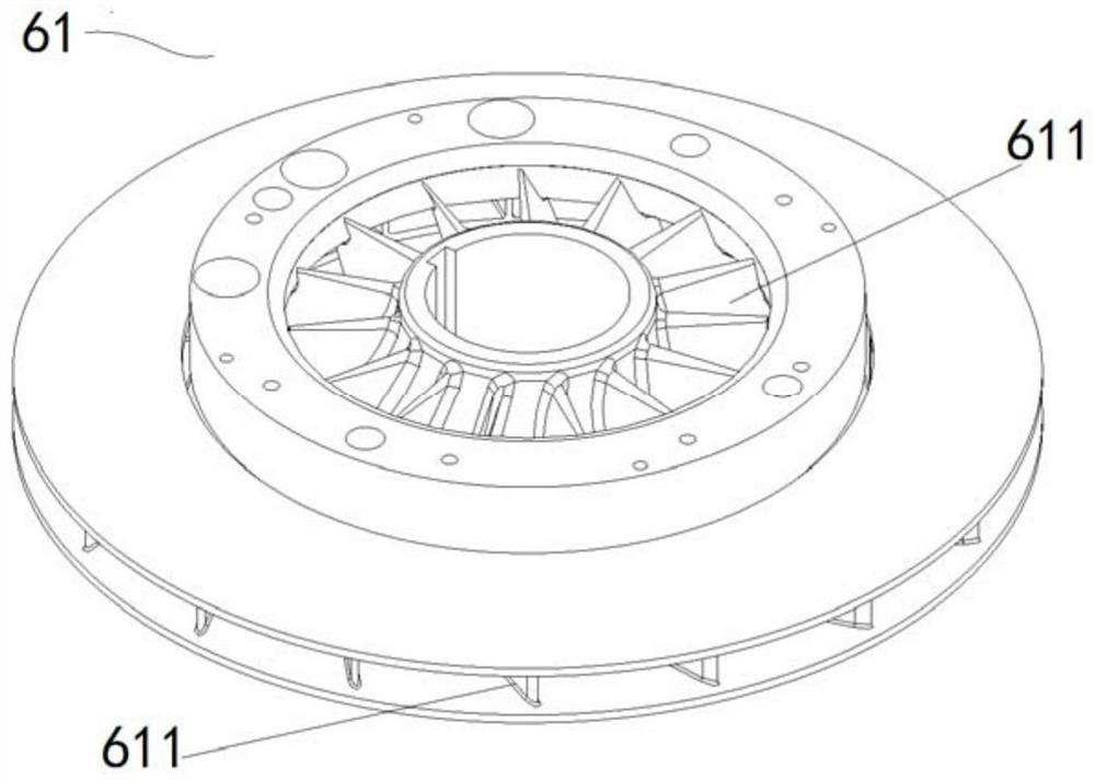
[0136] Specifically, the heating assembly 5 is set on the ring seat 41, and the rotating shaft sleeve 71 is extended along the central rod 3 to the depth of the vulcanization bladder 2, so that the air outlet 61 of the gas circulation assembly 6 is located above the heating assembly 5, and the ring The position of the seat 41 corresponding to the lower part of the heating assembly 5 is set in a conical shape of flow guide, which is convenient to guide the heating medium gas.

[0137] Further, as Figure 9 Shown is a schematic diagram of...


PUM


Abstract

The invention relates to the technical field of vulcanizing devices, in particular to vulcanizing equipment which comprises a vulcanizing mold, a vulcanizing device and a vulcanizing device. The vulcanizing capsule is suitable for being placed in the vulcanizing cavity; the supporting assembly comprises a center rod and a clamping device arranged on the center rod, and the clamping device is suitable for installing the curing bladder in the cavity in a sealed mode; the device further comprises a heating assembly and a gas circulation assembly, the heating assembly and the gas circulation assembly are arranged in the curing bladder in a stacked mode in the axial direction of the center rod, and the gas circulation assembly is suitable for enabling a heated heating medium to circulate in the curing bladder in a circulating mode. The driving assembly comprises a rotating shaft sleeve which is arranged on the outer side of the center rod in a clearance fit mode and connected with the gas circulation assembly. The invention provides vulcanizing equipment which overcomes the defects that in the prior art, equipment with horizontally-arranged vulcanizing capsules occupies too large space, the processing specification of vulcanized tires is limited, and gas circulation in the vulcanizing capsules is not facilitated.

Description

technical field [0001] The invention relates to the technical field of vulcanization devices, in particular to a vulcanization device. Background technique [0002] In industrial production, vulcanization is usually used to increase the overall hardness of certain materials. [0003] Taking tire vulcanization as an example, tire vulcanization refers to the vulcanization of the outer tire, which is vulcanized by means of model pressure. Before vulcanization, the tire is a plastic rubber with viscoelasticity, which is easy to deform, has low strength, and has no use value. Through vulcanization, the plastic rubber is cured and becomes a highly elastic rubber with useful value. [0004] The conventional tire curing process uses a combination of saturated steam and nitrogen. Specifically, the green tire is placed between the sealed vulcanization bladder 2 and the vulcanization mold, saturated steam is introduced into the vulcanization bladder 2 to provide the heat required for...

Claims


Application Information

Patent Timeline
Patent Type & Authority Applications(China)
IPC IPC(8): B29D30/06
CPCB29D30/0662B29D30/0606B29D2030/067B29D2030/0674B29D2030/0669B29D2030/0667B29D30/0654B29D2030/0658B29D2030/0659
Inventor 张伟赵阳刘志兰孙日文高龙飞方强刘代平
Owner HIMILE MECHANICAL SCI & TECH (SHANDONG) CO LTD
Learn More