Ejection mixer and control method thereof

A mixer and lobe technology, applied in the field of injection mixer and its control, can solve the problems of limited adjustment ability and large loss, and achieve the effect of enhancing ejection ability and improving uniformity

Pending Publication Date: 2022-03-15
BEIHANG UNIV
View PDF3 Cites 2 Cited by
  • Summary
  • Abstract
  • Description
  • Claims
  • Application Information

AI Technical Summary

Problems solved by technology

[0006] To sum up, some of the existing design patents for variable-area duct ejectors focus on the realization of the adjustment function of the flow area of ​​the rear duct, and the connotation and connotation are mixed, or the hole is incident, and the adjustment ability is limited; or the connotation is adopted. The airflow is incident at a near right angle, and the loss is relatively large
The rear variable area duct ejector, as the intermediary part connecting the turbo duct and the afterburner, should have the ability to efficiently mix the internal and external airflow after the turbine with low loss, and facilitate the organization of the afterburner. It is relatively lacking in the existing rear variable area duct ejectors

Method used


Image

  • Ejection mixer and control method thereof
  • Ejection mixer and control method thereof
  • Ejection mixer and control method thereof

Examples


Embodiment Construction

[0031] Various exemplary embodiments of the present invention will be described in detail below with reference to the accompanying drawings. The description of the exemplary embodiments is illustrative only, and not taken as any limitation of the invention, its application or uses. The present invention can be implemented in many different forms and is not limited to the embodiments described here. Rather, these embodiments are provided so that this disclosure will be thorough and complete, and will fully convey the scope of the invention to those skilled in the art. It should be noted that unless specifically stated otherwise, the relative arrangement of components and steps set forth in these embodiments should be construed as illustrative only and not as limiting.

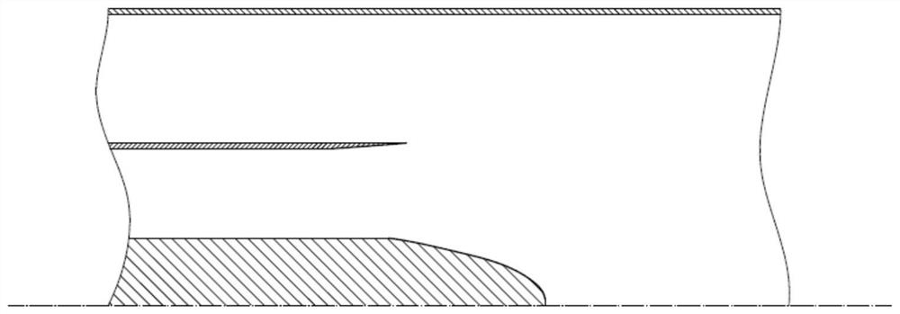
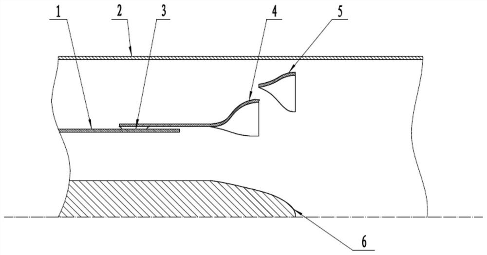
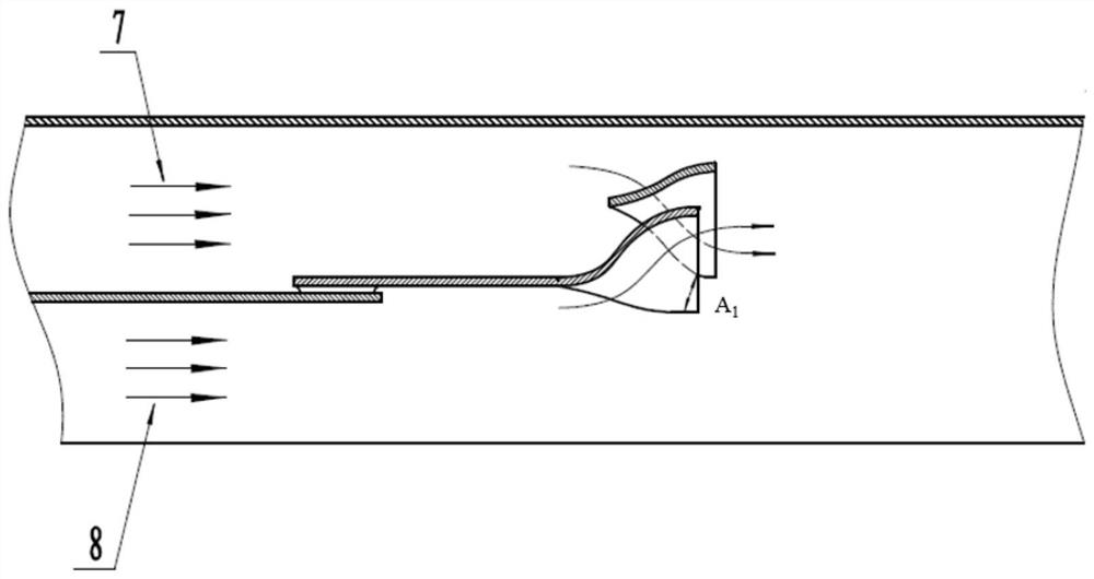
[0032] Such as Figure 1-10 Shown, in one aspect of the present invention, provide a kind of ejector mixer, comprise shunt ring, one-stage lobe mixer and two-stage lobe mixer, the circle center of shunt ring, ...


PUM


Abstract

The invention provides an injection mixer which is applied to a variable cycle engine and mainly structurally comprises a two-stage lobe mixer driven by an actuating device and used for strengthening mixing of inner culvert airflow and outer culvert airflow. The two stages of lobe mixers are arranged in a series connection mode, and the axial distance between the two stages of lobe mixers is changed through the actuating device, so that the interstage flow area of the lobe mixers is changed, and the function that the duct flow capacity is adjusted through the rear variable-area duct ejector is achieved. Compared with an annular mixer, the characteristic that the lobe mixer has higher mixing capacity on airflow is utilized, under the condition that the function that the rear variable ejector changes the circulation area of the outer culvert is achieved, the mixing quality of the inner culvert airflow and the outer culvert airflow behind the turbine is improved, the outlet temperature distribution of the ejection mixer is more uniform, and the mixing efficiency is improved. And favorable conditions are provided for combustion organization of a downstream afterburner. The invention further provides a control method of the injection mixer.

Description

technical field [0001] The invention belongs to the technical field of aviation gas turbine engines in aerospace technology, and in particular relates to an ejector mixer and a control method thereof. Background technique [0002] The concept of variable cycle engine appeared in the 1970s and has become an excellent choice for the next generation of high-performance aeroengines. The variable cycle engine completes the conversion of different thermodynamic cycle modes through a geometrically adjustable mechanism. The rear variable-area duct ejector is located at the junction of the inner turbine outlet and the outer duct, and realizes the functions of adjusting duct area and static pressure balance. The rear variable-area duct ejector plays an important role as a link to complete the mode switching with variable circulation and maintain high-efficiency operation. [0003] The development of variable-cycle engines is led by the United States, which has completed a number of ...

Claims


Application Information

Patent Timeline
Patent Type & Authority Applications(China)
IPC IPC(8): F02K1/30
CPCF02K1/30
Inventor 刘玉英蒲陶刘广海谢奕
Owner BEIHANG UNIV
Why Eureka
Try Eureka