
Sliding table type laser displacement sensor and sensor system comprising same

A laser displacement and sensor technology, used in instruments, optical devices, measuring devices, etc., can solve the problems of poor accuracy, deformation and bending of rods, affecting the use effect, etc., to achieve accurate measurement results, and ensure the effect of accuracy and stability.

Inactive Publication Date: 2022-03-15
RAILWAY ENG RES INST CHINA ACADEMY OF RAILWAY SCI +1
View PDF6 Cites 0 Cited by
  • Summary
  • Abstract
  • Description
  • Claims
  • Application Information

AI Technical Summary

Problems solved by technology

[0002] At present, drawstring displacement sensors, magnetostrictive displacement sensors and laser displacement sensors are generally used to measure the displacement of supports in bridge health monitoring systems; The telescopic pull rope makes the internal spring deformed and cannot rebound, which affects the use effect; when the magnetostrictive displacement sensor measures the displacement of the bridge support, the rod is deformed and bent due to the influence of forces in different directions on the bridge; the laser displacement sensor is due to Its own range limitation, in the long-term monitoring of the bridge, the range can not meet the demand, and when using a large-range laser displacement sensor, the accuracy is often relatively poor, the measurement value of long-term monitoring will produce large errors, and the measurement effect is not ideal

Method used


Image

  • Sliding table type laser displacement sensor and sensor system comprising same
  • Sliding table type laser displacement sensor and sensor system comprising same
  • Sliding table type laser displacement sensor and sensor system comprising same

Examples


Embodiment 1

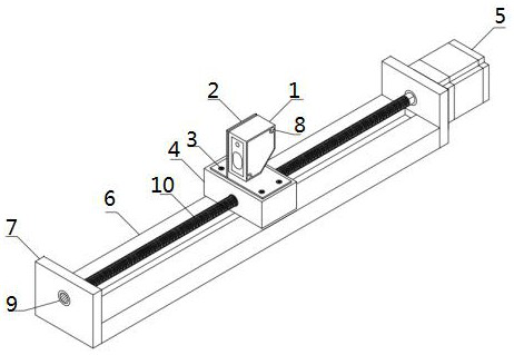
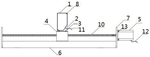
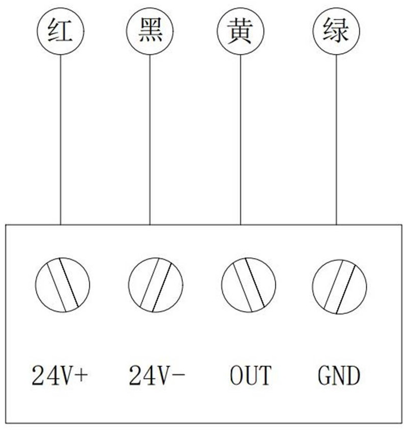
[0031] Slide table type laser displacement sensor provided by the present invention, as Figure 1 to Figure 2 As shown, the sliding table laser displacement sensor includes: a sliding table and a laser emitter 1, the laser emitter 1 is arranged on the sliding table, and the sliding table is used to drive the laser emitter 1 to move on the sliding table, and the sliding table includes a slide rail base 6 , ball screw 10, ball screw support 7, connecting piece, laser transmitter cable 11, motor cable 12 and motor 5, ball screw support 7 is fixedly connected to both sides of slide rail base 6, ball wire The rod 10 is erected between the two ball screw supports 7, the ball screw 10 is rotationally connected with the two ball screw supports 7, and one end of the ball screw 10 passes through the ball screw supports 7 to drive and connect with the motor 5, and the motor 5 is fixedly connected with the ball screw support 7, the motor 5 and the ball screw support 7 can be fixedly conne...

Embodiment 2

[0039] The sliding table type laser displacement sensor system provided by the present invention includes: the sliding table type laser displacement sensor and the controller of embodiment 1, the controller can adopt a PLC controller or a single chip microcomputer, and the sliding table type laser displacement sensor passes through the laser transmitter cable 11 and the motor The cable 12 is electrically connected with the controller, and the controller is used to calculate the displacement of the measured object and control the distance between the laser emitter 1 and the measured object. The distance signal collected by the laser transmitter 1 is a voltage signal, and a threshold value is set for the voltage signal, and the threshold value is 0-5V. When the voltage signal exceeds the threshold, the controller controls the motor 5 to rotate, the motor 5 drives the ball screw 10 to rotate, and the ball screw 10 drives the slider 4 and the laser emitter 1 to move until the volta...


PUM


Abstract

The invention discloses a sliding table type laser displacement sensor and a sensor system comprising the sliding table type laser displacement sensor, the sliding table type laser displacement sensor comprises a sliding rail base, a ball screw, ball screw supporting pieces and a motor, the ball screw supporting pieces are fixedly connected to the two sides of the sliding rail base, the ball screw is erected between the two ball screw supporting pieces, and the motor is arranged on the sliding rail base. The ball screw is rotationally connected with the ball screw supporting piece, the ball screw is in driving connection with the motor, the motor is fixedly connected with the ball screw supporting piece, the ball screw is sleeved with the sliding block, the sliding block is fixedly connected with the laser transmitter, and the laser transmitter is used for collecting distance signals between the laser transmitter and a measured object. The sliding table type laser displacement sensor has the advantages of being simple in structure, convenient to install, high in reliability and flexible and accurate in measurement process.

Description

technical field [0001] The invention relates to the technical field of bridge health monitoring, in particular to a slide-type laser displacement sensor and a sensor system comprising the same. Background technique [0002] At present, drawstring displacement sensors, magnetostrictive displacement sensors and laser displacement sensors are generally used to measure the displacement of supports in bridge health monitoring systems; The telescopic pull rope makes the internal spring deformed and cannot rebound, which affects the use effect; when the magnetostrictive displacement sensor measures the displacement of the bridge support, the rod is deformed and bent due to the influence of forces in different directions on the bridge; the laser displacement sensor is due to Its own range limitation, in the long-term monitoring of the bridge, the range cannot meet the demand, and the accuracy is often relatively poor when using a large-range laser displacement sensor, the measuremen...

Claims


Application Information

Patent Timeline
IPC IPC(8): G01B11/02
CPCG01B11/02
Inventor 鞠晓臣尹京苏永华赵欣欣郭辉肖鑫王丽李彬洋向琪芪陈令康左照坤
Owner RAILWAY ENG RES INST CHINA ACADEMY OF RAILWAY SCI
Learn More