Cable laying device

A cable laying and cable technology, applied in the field of cable laying devices, can solve the problems of low automation of cable laying, affecting the normal pulling and laying of cables, translation and skewing, etc.

Inactive Publication Date: 2022-03-15
嘉兴市平安电气工程有限公司
View PDF0 Cites 0 Cited by
  • Summary
  • Abstract
  • Description
  • Claims
  • Application Information

AI Technical Summary

Problems solved by technology

In the construction work of cable laying, in order to avoid scratching and damage caused by the friction between the cable and the ground, the cable laying bracket is usually used to support and guide the cable. During the use of the cable laying bracket, it is difficult for the cable laying bracket to be stable and effective. The supporting positioning of the cable is often caused by the translation and skew due to the tension of the cable laying, which affects the continuous and stable normal pulling and laying of the cable, and the existing cable laying is carried out by human pulling, and the unwinding of the cable is realized by using human pulling. Laying, the labor intensity of workers is relatively high, and the degree of automation of cable laying is low. It is difficult to achieve efficient and smooth pulling and laying of cables, which cannot meet the needs of cable laying and use.

Method used


Image

  • Cable laying device
  • Cable laying device
  • Cable laying device

Examples


Embodiment Construction

[0015] In order to further describe the present invention, a specific implementation of a cable laying device will be further described below in conjunction with the accompanying drawings. The following examples are explanations of the present invention and the present invention is not limited to the following examples.

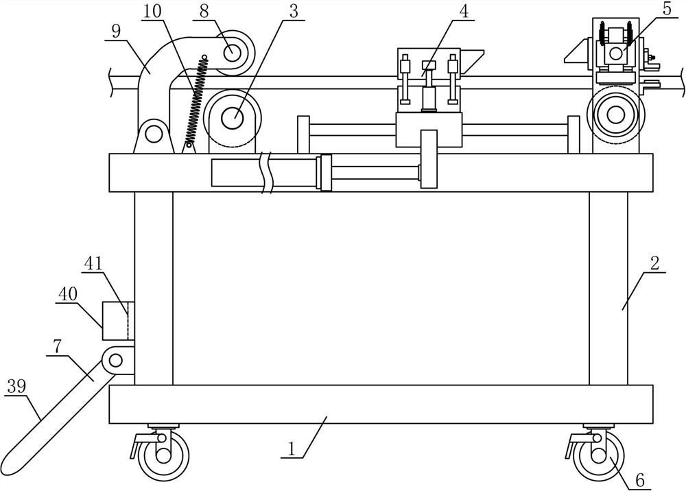
[0016] like figure 1 As shown, a cable laying device of the present invention includes a cable laying base 1, a cable laying support 2, a cable transmission guide roller 3, a cable pulling mechanism 4 and a cable clamping mechanism 5, and the lower side of the cable laying base 1 is uniformly arranged with multiple A universal wheel 6 with a brake, the cable laying bracket 2 is horizontally and fixedly arranged on the upper side of the cable laying base 1, the cable transmission guide roller 3, the cable pulling mechanism 4 and the cable clamping mechanism 5 are successively arranged on the cable laying bracket 2 along the horizontal direction On the upper si...


PUM


Abstract

The invention discloses a cable laying device, and belongs to the field of electric power engineering equipment. A cable laying support is horizontally and fixedly arranged on the upper side of a cable laying base, a laying positioning mechanism is arranged on the cable laying support along the lower portion of the side of a cable conveying guide roller, the cable conveying guide roller is horizontally and rotationally connected to one side of the upper portion of the cable laying support, and a reciprocating translation guide plate is arranged on a cable pulling and conveying guide rod in a sliding mode in the horizontal direction. The upper pulling and conveying pressing plate is horizontally arranged on the upper side of the lower pulling and conveying bearing plate, a translation pushing wedge plate is horizontally and fixedly arranged on the upper pulling and conveying pressing plate along the cable clamping mechanism side, and the cable clamping pressing plate is horizontally arranged on the upper side of the cable laying guide roller. And the cable clamping pressing plate is horizontally and fixedly provided with a bearing and pushing lifting wedge plate matched with the translation pushing wedge plate along the cable pulling and conveying mechanism side. The cable laying device is reasonable in structural design and stable in operation and use, cables can be efficiently and smoothly pulled and laid section by section, the automation degree of cable laying is improved, and the use requirement is met.

Description

technical field [0001] The invention belongs to the field of electric engineering equipment, in particular to a cable laying device. Background technique [0002] With the rapid development of modern city construction and economy, cables are widely used in daily production and life. Cables can mainly be used in power systems, information transmission systems and instrument control systems. Cable laying refers to laying along surveyed routes, The process of installing cables to form cable lines, according to the use occasions, cable laying can be divided into several laying methods such as overhead laying, underground pipeline laying, direct burial laying, underwater laying, wall laying and tunnel laying. It is very important to ensure the transmission quality, reliability and construction maintenance of the line. In the construction of urban power distribution network, it is necessary to carry out the construction of power cables for distribution network projects and communi...

Claims


Application Information

Patent Timeline
Patent Type & Authority Applications(China)
IPC IPC(8): H02G1/06H02G1/08
CPCH02G1/06H02G1/081
Inventor 方浩黄伟强钱亚婧施秋婷方永强闻秋霞
Owner 嘉兴市平安电气工程有限公司
Why Eureka
Try Eureka