
Adapter for clip applier and clip applier

An adapter and clip applier technology, applied in the field of medical devices, can solve the problems of inconvenient installation and disassembly of a clip compartment component, inconvenient operation for users, complicated structure of the connecting part, etc., so as to improve safety and reliability, prevent insertion The effect of unplugging error and convenient plugging and unplugging

Pending Publication Date: 2022-03-18
SUZHOU YINGTUKANG MEDICAL TECH CO LTD
View PDF0 Cites 2 Cited by
  • Summary
  • Abstract
  • Description
  • Claims
  • Application Information

AI Technical Summary

Problems solved by technology

When the clip assembly and the adapter are installed and disassembled, the connection part between the adapter and the clip assembly has a complex structure, which is not convenient for the installation and disassembly of the clip assembly, and thus inconvenient for the user to operate, resulting in low work efficiency

Method used


Image

  • Adapter for clip applier and clip applier
  • Adapter for clip applier and clip applier
  • Adapter for clip applier and clip applier

Examples


Embodiment 1

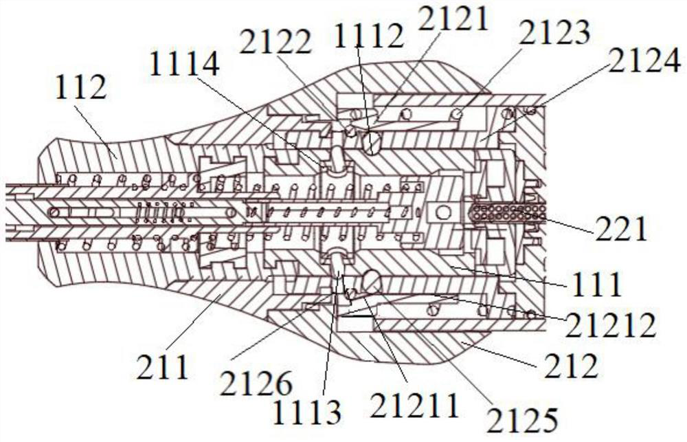
[0038] Such as Figure 1-Figure 9 As shown, this embodiment provides a clip applier, which includes a clip bin assembly 1 and an adapter 2 .

[0039] Among them, such as figure 1 and Figure 5 As shown, the clip assembly 1 includes a clip shell 11 , a rod body 12 and an end effector 13 .

[0040] In this embodiment, the clip housing 11 is set as two relatively rotating housings, that is, the clip housing 11 includes a clip fixing housing 111 and a clip rotating housing 112, and the clamp rotating housing 112 is rotatably connected. At the far end of the clip fixing housing 111 , the near end of the clip fixing housing 111 is provided with an identification signal generating structure for establishing communication with the identification signal receiver fixedly installed in the adapter 2 . A communicating accommodating cavity is provided in the clip fixing housing 111 and the clip rotating housing 112 . In this embodiment, both the clamp fixing housing 111 and the clamp ro...

Embodiment 2

[0109] refer to Figure 10 , The difference between this embodiment and Embodiment 1 is that the auxiliary locking mechanism is different. Specifically, in this embodiment, the auxiliary locking mechanism includes at least one set of mushroom-shaped buckles 1117 and an elastic seat 1118, and the magazine fixing shell 111 is provided with a reverse formed by connecting a wide hole on the inside and a narrow hole on the outside. The trapezoidal groove, the elastic seat 1118 is fixed in the wide hole, the elastic seat 1118 can be any connecting piece that can provide elasticity such as springs, rubber pads, etc., the mushroom-shaped buckle 1117 includes a hemispherical head and a support portion located inside the hemispherical head , the supporting part is connected between the hemispherical head and the elastic seat 1118, and in the free state, the hemispherical head of the mushroom-shaped buckle 1117 enters the positioning hole 2126 through the narrow hole to form an auxiliary...


PUM


Abstract

The invention belongs to the technical field of medical instruments, and particularly relates to an adapter for a clip applier and the clip applier. The clip applier comprises a clip bin assembly and an adapter, a locking structure is arranged in the clip bin assembly, the adapter comprises an adapter shell and a locking mechanism, and an operating piece on the adapter shell moves towards the near end direction under the action of external force towards the near end direction. Urging the locking mechanism to allow a clip cartridge assembly of the clip applier to be inserted into and pulled out of the adapter housing; when the external force towards the near-end direction disappears, the locking mechanism enables the operation piece to move to the original position towards the far-end direction and can be matched with the locking structure on the clamping bin assembly, and the clamping bin assembly is locked in the adapter. Therefore, the clamping bin assembly is convenient to mount and dismount and has a fool-proof effect.

Description

technical field [0001] The invention belongs to the technical field of medical instruments, in particular to an adapter for a clip applier and a clip applier. Background technique [0002] Surgical clip appliers are commonly used to clamp tubular tissue during surgery to prevent fluid leakage within the tubular tissue. [0003] In the prior art, the clip magazine assembly of the clip applier is detachably installed on the adapter of the clip applier and establishes communication with the adapter. The adapter will identify the information of the clips in the clip magazine assembly so as to execute corresponding program actions. When the clip assembly and the adapter are installed and disassembled, the structure of the connection part between the adapter and the clip assembly is complex, which is inconvenient for the installation and disassembly of the clip assembly, and thus inconvenient for the user to operate, resulting in low work efficiency. Contents of the invention ...

Claims


Application Information

Patent Timeline
Patent Type & Authority Applications(China)
IPC IPC(8): A61B17/128
CPCA61B17/1285
Inventor 徐荣华
Owner SUZHOU YINGTUKANG MEDICAL TECH CO LTD
Learn More