Sighting device of bone penetrating fixing needle

A technology for fixing a needle and an aimer, applied in the field of medical devices, can solve the problem of low accuracy of the aimer, and achieve the effect of improving the accuracy

Pending Publication Date: 2022-03-18
BEIJING JISHUITAN HOSPITAL
View PDF0 Cites 0 Cited by
  • Summary
  • Abstract
  • Description
  • Claims
  • Application Information

AI Technical Summary

Problems solved by technology

[0005] The object of the present invention is to provide a collimator for bone

Method used


Image

  • Sighting device of bone penetrating fixing needle
  • Sighting device of bone penetrating fixing needle
  • Sighting device of bone penetrating fixing needle

Examples


Embodiment 1

[0030] Embodiment 1: A kind of collimator of bone penetrating fixation needle

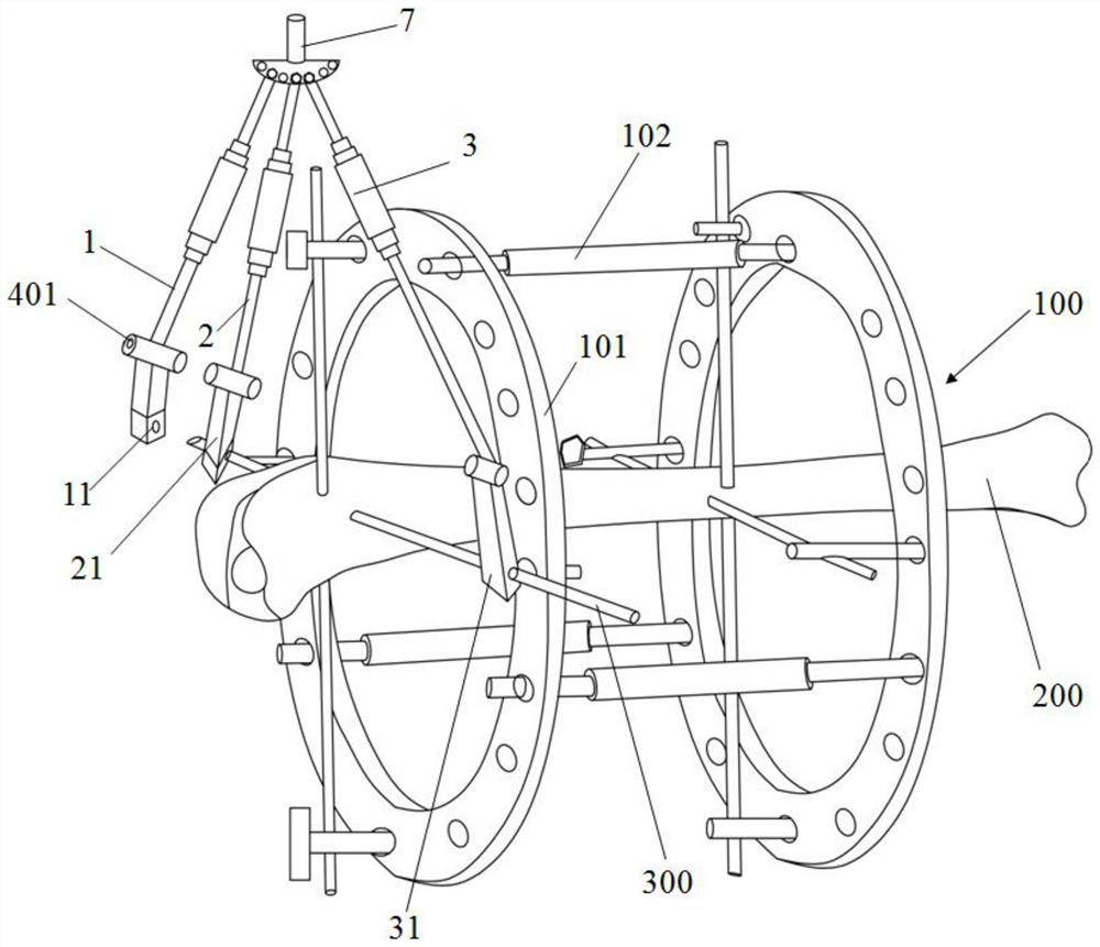
[0031] Embodiment 1 provides a collimator for a bone-piercing fixation needle, which is used to fix the bone-piercing fixation needle 300 on the fixing ring 101 of the external fixator 100 , and its structure will be described in detail below.

[0032] refer to figure 1 , the external fixator 100 includes two fixing rings 101, each fixing ring 101 is provided with a plurality of bolt holes at intervals in the circumferential direction, the fixing rings 101 are parallel to each other, and the two fixing rings 101 are detachable through three connecting rods 102 connect. Specifically, the connecting rod 102 is a threaded screw rod, and the connecting rod 102 is passed through the bolt hole of the fixing ring 101, and fixed by a matching nut, so that the two fixing rings 101 and the three connecting rods 102 are connected by bolts. An external fixator 100 is assembled.

[0033] refer to Figure 1 ...

Embodiment 2

[0052] Embodiment 2: A method of using a collimator of a bone penetrating fixation needle

[0053] Embodiment 2 provides a method of using the collimator of a bone-piercing fixation needle, using the collimator of a bone-piercing fixation needle in Embodiment 1, and the method of use includes an installation method and a disassembly method.

[0054] Wherein, the installation method includes the following steps:

[0055] On the fixed ring 101, select the starting bolt hole and the ending bolt hole as the positions of the starting point and the ending point respectively;

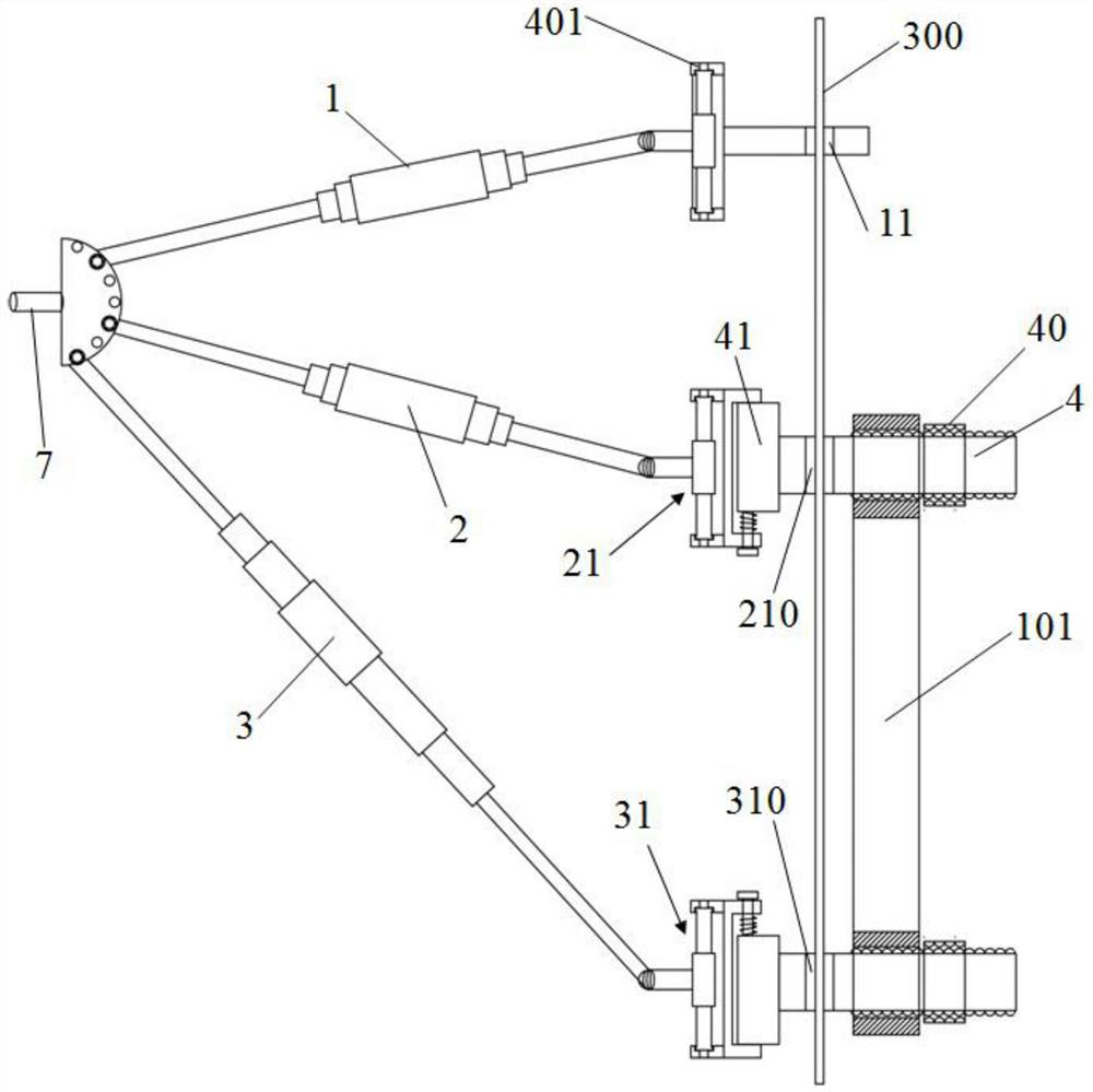
[0056] The starting rod fixing ring connecting device 21 and the ending rod fixing ring connecting device 31 are respectively connected to the starting bolt hole and the ending bolt hole of the fixing ring 101 by bolts, and the bottom ends of the starting rod 2 and the ending rod 3 are respectively connected to the The connecting device 21 for the fixing ring of the starting rod and the connecting device 31 f...

Embodiment 3

[0069] Embodiment 3: Another kind of aimer for bone penetrating fixation needle

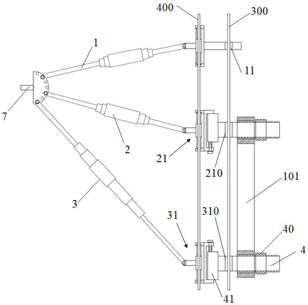
[0070] Compared with the defect that the starting rod 2 and the terminating rod 3 obstruct the line of sight or operation when performing the bone penetrating operation in the embodiment 1, the embodiment 3 adjusts the aiming rod 1, the starting rod 2 and the terminating rod on the basis of the embodiment 1. 3 and the connection relationship between the starting rod 2, the ending rod 3 and the fixing ring 101 have been improved, the starting rod 2 and the ending rod 3 no longer rotate relative to the fixing ring 101, but lie flat on the fixing ring 101 Specifically, the improvement lies in:

[0071] refer to Figure 6 , the aiming rod 1 , the starting rod 2 and the ending rod 3 are attached to the fixing ring 101 of the external fixator 100 to ensure that the three rods of the aiming rod 1 , the starting rod 2 and the ending rod 3 are coplanar.

[0072] The aiming rod 1 , the starting rod 2 and...


PUM


Abstract

The sighting device of the bone penetrating fixing needle comprises a sighting rod, a starting rod and a stopping rod, and the sighting rod, the starting rod and the stopping rod are connected together through the top ends to achieve coplanarity and rotation of the three rods; the starting rod and the stopping rod of the aiming rod are provided with an aiming hole, a starting needle hole and a stopping needle hole respectively, the aiming rod, the starting rod and the stopping rod are all telescopic rods, and the positions of the three holes in the same plane are adjusted by adjusting the lengths of the aiming rod, the starting rod and the stopping rod and rotating the three rods, so that it is guaranteed that when a bone penetrating fixing needle is arranged in a penetrating mode, the bone penetrating fixing needle is fixed. The aiming hole, the starting pinhole and the ending pinhole are located on the same straight line. According to the sighting device of the bone penetrating fixing needle, the accuracy of the bone penetrating fixing needle along the straight line in the bone penetrating process is improved, and the starting point and the end point of the bone penetrating fixing needle on the fixing ring and the penetrating point of the bone penetrating fixing needle on the bone can meet the requirement that the starting point and the end point are collinear; and the bone penetrating fixing needle can reach the accurate position of the fixing ring according to the specified position.

Description

technical field [0001] The invention relates to the technical field of medical instruments, in particular to an aimer for a bone-piercing fixation needle. Background technique [0002] At present, steel needles such as Kirschner wires and Steiner wires are often used as bone-piercing fixation pins, and bone and external fixator are connected by implanting bone-piercing fixation pins. [0003] The entry point and end point of the fixation pin fixed on the ring and the point where the pin penetrates the bone must be in a straight line, otherwise the pin will bend and lose tension The effect of fixation leads to loosening of fixation and failure of orthopedic surgery. [0004] In order to achieve the collinear requirements of the entry point and end point of the fixation pin fixed on the ring and the penetration point of the fixation pin on the bone, it is necessary to use a collimator. However, the accuracy of the current aimer is low, so that the aimer cannot pass through t...

Claims


Application Information

Patent Timeline
IPC IPC(8): A61B17/60A61B17/62
CPCA61B17/60A61B17/62
Inventor 徐云峰闫桂森冯超杨征张骥尤海峰吕学敏傅刚边臻
Owner BEIJING JISHUITAN HOSPITAL
Why Eureka
Try Eureka