Labeling device for glass bottles

A glass bottle and labeling technology, applied in labeling, labeling machines, labels, etc., can solve problems such as low productivity and inability to guarantee labeling quality, and achieve the effect of ensuring labeling quality

Pending Publication Date: 2022-03-18
刘齐花
View PDF0 Cites 0 Cited by
  • Summary
  • Abstract
  • Description
  • Claims
  • Application Information

AI Technical Summary

Problems solved by technology

[0004] In order to overcome the shortcomings of manual labeling, low productivity, and inability to guarantee the quality of labeling, the technical problem is to provide a labeling device for glass bottles that does not require manual labeling, has high productivity, and ensures the quality of finished products

Method used


Image

  • Labeling device for glass bottles
  • Labeling device for glass bottles
  • Labeling device for glass bottles

Examples


Embodiment 1

[0078] A labeling device for glass bottles, such as Figure 1-2 As shown, it includes a base 1, a first support frame 2, a servo motor 3, a second support frame 4, a third support frame 5, a first rotating shaft 6, a collection drum 7, a storage drum 8, and a connecting block 9 , a labeling block 10, a rotating mechanism 11 and a fitting mechanism 12, a first support frame 2 is provided on the front side of the top of the base 1, a servo motor 3 is provided on the top of the first support frame 2, and a second support is provided on the left side of the top of the base 1 frame 4, a third support frame 5 is provided in the middle of the top of the base 1, a first rotating shaft 6 is provided at the output end of the servo motor 3, and a collecting drum 7 and a rotating drum 7 are arranged between the second support frame 4 and the third support frame 5 The material storage drum 8 is connected with the first rotating shaft 6, the second support frame 4 is provided with a connect...

Embodiment 2

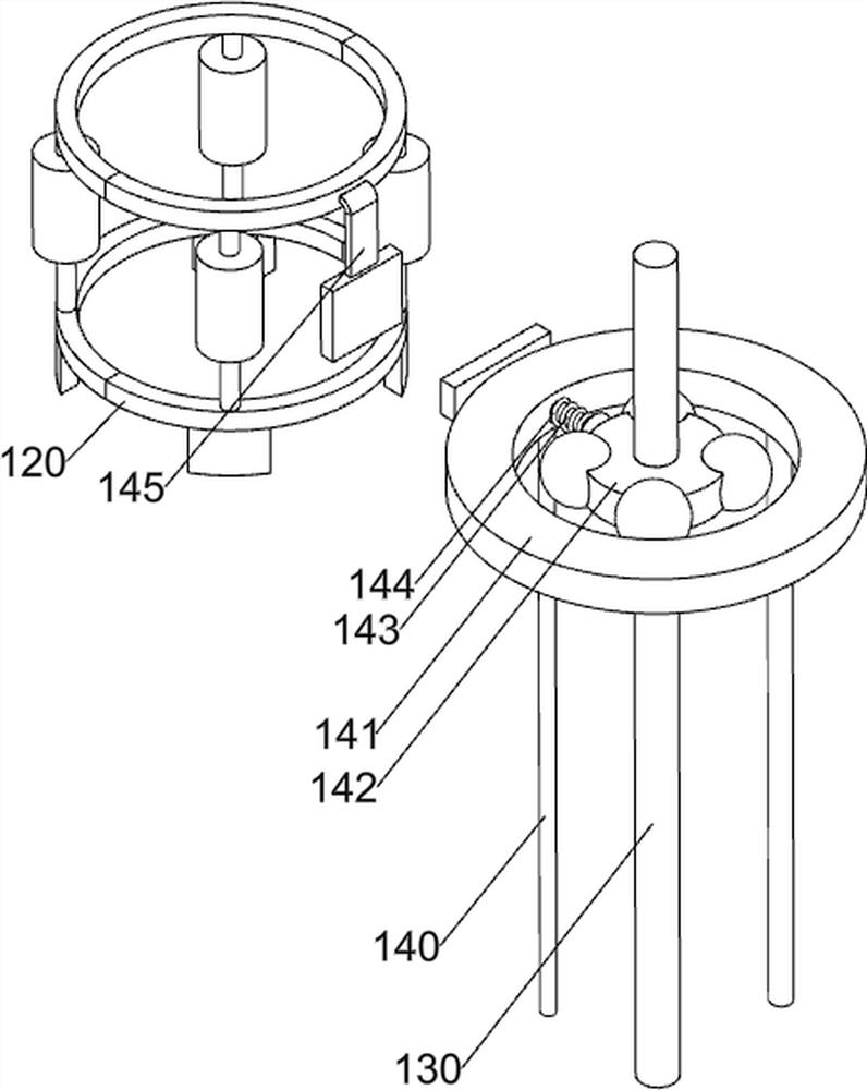
[0081] On the basis of Example 1, such as Figure 3-4 As shown, the rotating mechanism 11 includes a second rotating shaft 110, a first pulley assembly 111, a guide ring 112, a rotating disc 113 and a first support rod 114, and the left side of the base 1 is rotatably provided with a second rotating shaft 110, and the first rotating shaft 6 and the second rotating shaft 110 are provided with a first pulley assembly 111, the first pulley assembly 111 is composed of two pulleys and a belt, the two pulleys are respectively connected on the first rotating shaft 6 and the second rotating shaft 110, and the belt is wound on Between the pulleys, a rotating disk 113 is provided on the second rotating shaft 110, a first support rod 114 is provided on the left rear side of the top of the base 1, a guide ring 112 is provided on the first support rod 114, and the guide ring 112 and the rotating disk 113 slide connect.

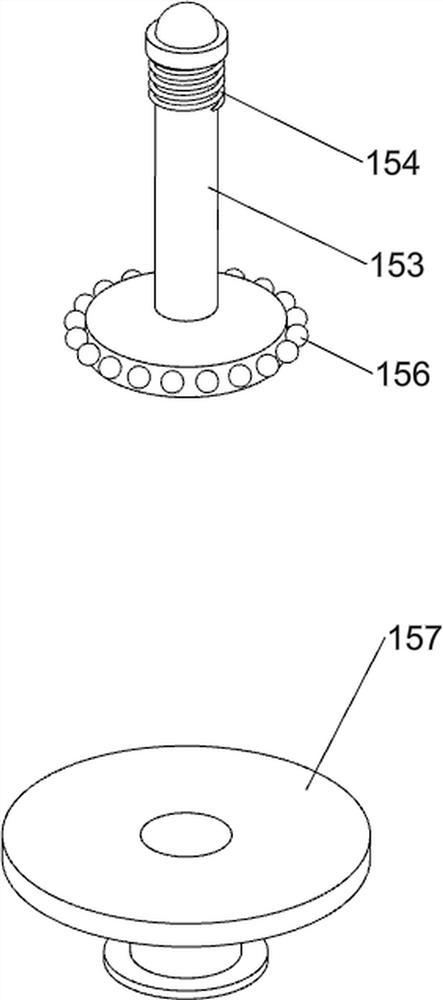
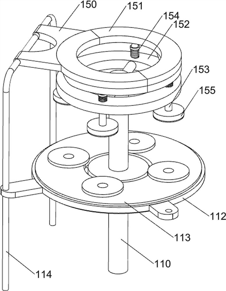
[0082] The bonding mechanism 12 includes a first connecting frame 12...

Embodiment 3

[0085] On the basis of Example 2, such as Figure 5-9 As shown, a feeding mechanism 13 is also included, and the feeding mechanism 13 includes a third rotating shaft 130, a second pulley assembly 131, a support plate 132, a distribution tray 133, a second connecting frame 134, a first limiting plate 135, a fourth Rotating shaft 136, the fifth rotating shaft 137, the third pulley assembly 138, bevel gear 139, limit frame 1310 and conveyor belt 1311, the middle rotating type of base 1 top is provided with the third rotating shaft 130, between the third rotating shaft 130 and the second rotating shaft 110 A second pulley assembly 131 is provided. The second pulley assembly 131 is composed of two pulleys and a belt. The two pulleys are respectively connected to the third rotating shaft 130 and the second rotating shaft 110. The belt is wound between the pulleys. The top of the base 1 is symmetrical Four support plates 132 are provided, and a fourth rotating shaft 136 is rotatably ...


PUM


Abstract

The invention relates to a labeling device, in particular to a labeling device for glass bottles. The invention provides the labeling device for the glass bottle, which does not need manual labeling, is high in productivity and ensures the quality of finished products. The labeling device for the glass bottle comprises a base used for installing the whole device; the first supporting frame is arranged on the front side of the top of the base; the servo motor is arranged at the top of the first supporting frame; the second supporting frame is arranged on one side of the top of the base; the third supporting frame is arranged in the middle of the top of the base; the output end of the servo motor is provided with the first rotating shaft. According to the labeling machine, the clamping mechanism and the attaching mechanism are matched, the clamping mechanism clamps the discharged bottles, so that labeling work is facilitated, the attaching mechanism makes contact with the bottles, labels are further attached, and the labeling quality is guaranteed.

Description

technical field [0001] The invention relates to a labeling device, in particular to a labeling device for glass bottles. Background technique [0002] At present, there is no labeling mechanism installed on the winding of the existing technology, so the automatic labeling of the battery cells cannot be realized. In addition, if manual labeling is performed, the defects of irregular operation, low productivity, time-consuming and labor-intensive and increased labor costs lead to increased production. At the same time, because it is not easy to fix the bottle body, the quality of the labeling cannot be guaranteed, and it is easy to cause a low yield. [0003] Therefore, there is a need for a labeling device for glass bottles that does not require manual labeling, has high productivity, and ensures the quality of finished products. Contents of the invention [0004] In order to overcome the shortcomings of manual labeling, low productivity, and inability to guarantee the qua...

Claims


Application Information

Patent Timeline
Patent Type & Authority Applications(China)
IPC IPC(8): B65C9/02B65C9/18B65C9/26B65C3/06
CPCB65C9/02B65C9/18B65C9/26B65C3/06
Inventor 刘齐花
Owner 刘齐花
Why Eureka
Try Eureka