
High-protection ammeter current transformer

A current transformer and high-protection technology, applied in the field of transformers, can solve problems such as inconvenient wiring and assembly of pins and shell structures, current signal errors, large measurement errors of transformers, etc. The value is stable and the effect of ensuring circuit contact

Pending Publication Date: 2022-03-18
宁波泰丰源电气有限公司
View PDF7 Cites 0 Cited by
  • Summary
  • Abstract
  • Description
  • Claims
  • Application Information

AI Technical Summary

Problems solved by technology

Because in AC lines, the influence of DC and even harmonics can produce large errors on current signals, especially under high-power loads, traditional transformers can filter their DC harmonics due to their unreasonable structure, and then Make the transformer produce a relatively large measurement error, and it is difficult to maintain high-precision measurement of the current
From the structural point of view, the current output of the existing current transformer uses a wire harness to directly insert into the circuit under test, resulting in an unreasonable design structure and inconvenient production. At the same time, the structure of the pin and the shell is inconvenient for wiring and assembly, and it is difficult to judge the accuracy of the connection circuit.

Method used


Image

  • High-protection ammeter current transformer
  • High-protection ammeter current transformer
  • High-protection ammeter current transformer

Examples


Embodiment Construction

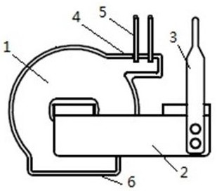
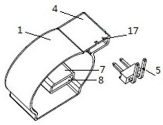
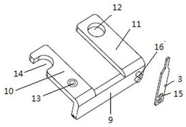
[0025] Such as Figures 1 to 5 As shown, the present invention includes a housing 1, a U-shaped transformer frame 2 and a voltage sampling needle 3. The cross-section of the housing is a closed shape formed by two U-shaped sections and two arc-shaped sections, wherein one U-shaped form constitutes the The bottom of the housing 1 is marked as the lower U-shaped 6, and its two ends are respectively connected with one end of the two arc-shaped bodies. The other end of the arc-shaped body is connected, and a cylindrical protrusion 7 is arranged inside the housing 1. The cylindrical protrusion 7 is integrated with the housing 1, and a circuit is arranged on the cylindrical protrusion 7. plate and induction coil. A rectangular hole 8 is provided in the cylindrical boss 7; the material of the housing 1 is insulating material, such as plastic material.

[0026] The U-shaped mutual induction frame 2 is provided with a bottom conductive block 9 placed horizontally, a left vertical con...


PUM


Abstract

The invention relates to a high-protection ammeter current transformer, which comprises a shell, a U-shaped mutual inductance frame and a voltage sampling needle, and is characterized in that the cross section of the shell is a closed body formed by two U-shaped sections and two arc-shaped sections, one U-shaped section forms the bottom of the shell and is marked as a lower U-shaped section, the two ends of the lower U-shaped section are respectively connected with one ends of the two arc-shaped sections, and the other end of the lower U-shaped section is connected with the other end of the two arc-shaped sections. One U shape is marked as an upper U shape, two ends of the other U shape are respectively connected with the other ends of the two arc-shaped bodies, a cylindrical convex column is arranged in the shell, the cylindrical convex column and the shell are integrated, and a rectangular hole is formed in the cylindrical convex column. According to the invention, the two probe holes of the voltage sampling probe are completely embedded with the bottom conductive block after installation and are tightly embedded with each other, so that the voltage value is stable, and the problem of poor contact is effectively solved. Meanwhile, the voltage sampling needle and the shell form a compact structure.

Description

technical field [0001] The invention relates to the technical field of transformers, in particular to a high-protection electric meter current transformer. Background technique [0002] The transformer is the main current signal acquisition part of the electric energy meter, and its performance will directly affect the measurement accuracy of the electric energy meter. Because in AC lines, the influence of DC and even harmonics can produce large errors on current signals, especially under high-power loads, traditional transformers can filter their DC harmonics due to their unreasonable structure, and then This causes relatively large measurement errors in the transformer, making it difficult to maintain high-precision measurement of the current. From the structural point of view, the current output of the existing current transformer is directly inserted into the circuit under test by using a wire harness, which leads to an unreasonable design structure and inconvenient pro...

Claims


Application Information

Patent Timeline
Patent Type & Authority Applications(China)
IPC IPC(8): G01R19/00G01R1/04
CPCG01R19/00G01R1/04
Inventor 袁郭竣章孟翼潘琳斌
Owner 宁波泰丰源电气有限公司
Learn More