
Display system and system controller

A system controller and display system technology, applied in the direction of static indicators, instruments, etc., can solve the problems of high cost, increased workload of control system program development, difficult reuse of customized LED display boxes, etc., and achieve simple system architecture Effect

Pending Publication Date: 2022-03-18
XIAN NOVASTAR TECH
View PDF13 Cites 2 Cited by
  • Summary
  • Abstract
  • Description
  • Claims
  • Application Information

AI Technical Summary

Problems solved by technology

For lessors, this kind of customized LED display cabinet is not easy to reuse, and the cost is high, and the workload of program development of the control system also increases accordingly.
In this way, in order to meet a certain scene, a specific LED display cabinet and a specific firmware program are required, resulting in very high costs for development, debugging, and maintenance
[0003] In addition, the existing screen rotation display scheme requires the cooperation of the receiving card (or module controller, scanning card) and can only achieve regular 90° rotation.

Method used


Image

  • Display system and system controller
  • Display system and system controller
  • Display system and system controller

Examples


no. 1 example

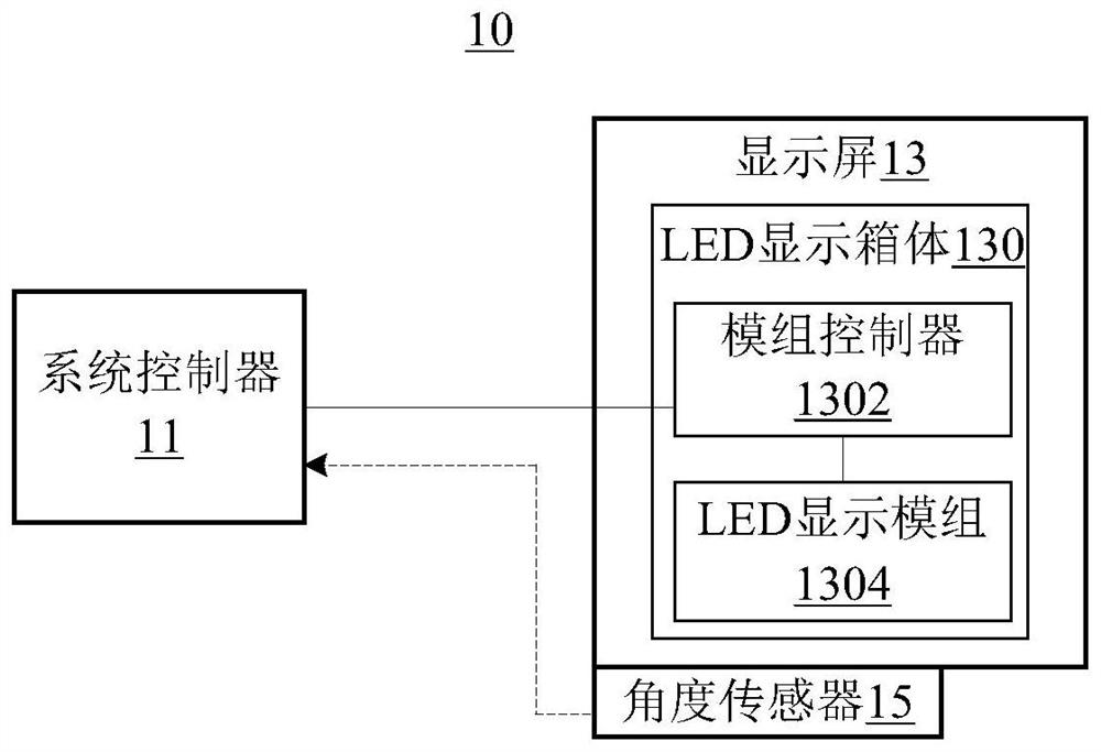
[0029] see figure 1 , a display system 10 provided by an embodiment of the present invention includes: a system controller 11 , a display screen 13 and an angle sensor 15 .

[0030] Wherein, the display screen 13 includes one or more LED display boxes 130 . Each of the LED display boxes 130 includes a module controller 1302 and an LED display module 1304 electrically connected to the module controller 1302 , and the module controller 1302 is electrically connected to the system controller 11 . Wherein, the LED display module 1304 may be an LED display light panel or a plurality of LED display light panels spliced ​​together, which typically use LED lights such as RGB three-color LED lights to form display pixels.

[0031] The angle sensor 15 is fixed on the display screen and connected to the system controller 11 for signals. For example, the number of the angle sensors 15 can be set to one or more according to actual needs. When the angle sensor 15 is one, it can be fixed ...

specific Embodiment approach 1

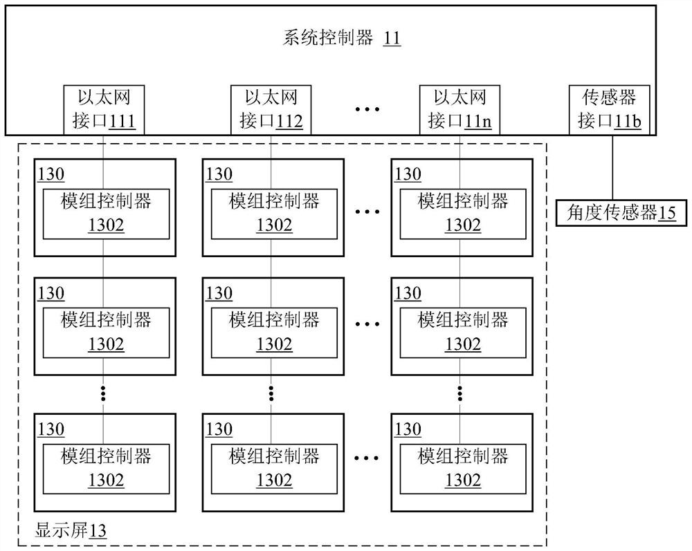
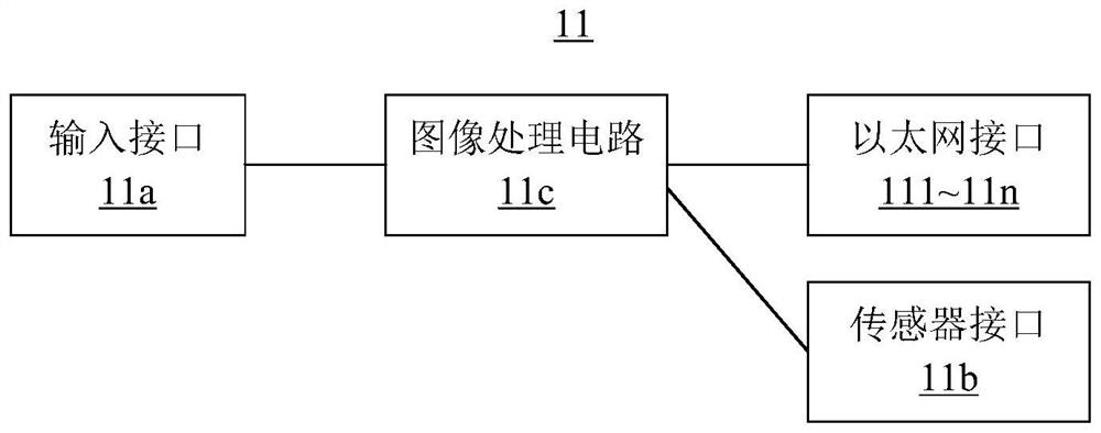
[0035] The first embodiment of the present embodiment is a situation in which the display screen 13 is rotated as a unit. Specifically, see Figure 2A , the system controller 11 is provided with a plurality of Ethernet interfaces 111, 112, ..., 11n and a sensor interface 11b, where the Ethernet interfaces 111, 112, ..., 11n can be Ethernet electrical ports, or can be Ethernet optical port. The display screen 13 includes a plurality of LED display boxes 130, for example including at least one ( Figure 2A Show a plurality of as an example) LED display box 130, at least one ( Figure 2A Show a plurality of as an example) LED display box 130 and at least one ( Figure 2A A plurality of LED display cabinets 130 are shown as an example. exist Figure 2A Among them, the respective module controllers 1302 of a plurality of LED display cabinets 130 carried by the same Ethernet interface (any one of 111, 112, ..., 11n) are electrically connected to the Ethernet interface in a casc...

specific Embodiment approach 2

[0038] The second embodiment of the present invention is a situation in which the LED display box is rotated as a unit. Specifically, see Figure 3A , the system controller 11 is provided with a plurality of Ethernet interfaces 111, 112, ..., 11n, where the Ethernet interfaces 111, 112, ..., 11n may be Ethernet electrical ports or Ethernet optical ports. The display screen 13 includes a plurality of LED display boxes 130, for example including at least one ( Figure 3A Show a plurality of as an example) LED display box 130, at least one ( Figure 3A Show a plurality of as an example) LED display box 130 and at least one ( Figure 3A A plurality of LED display cabinets 130 are shown as an example. exist Figure 3A Among them, the respective module controllers 1302 of a plurality of LED display cabinets 130 carried by the same Ethernet interface (any one of 111, 112, ..., 11n) are electrically connected to the Ethernet interface in a cascade manner . Each LED display box 1...


PUM


Abstract

The embodiment of the invention discloses a display system and a system controller thereof. The display system, for example, includes: a system controller; the display screen comprises an LED display box body, the LED display box body comprises a module controller and an LED display module electrically connected with the module controller, and the module controller is electrically connected with the system controller; the angle sensor is fixed on the display screen and is in signal connection with the system controller; wherein the system controller is used for carrying out rotation processing on an input image according to angle information which is sensed by the angle sensor and is related to the display screen to obtain a processed image, and sending the processed image to the module controller of the LED display box body so as to drive and control the LED display module to carry out image display. The embodiment of the invention can realize rotary display of the screen body based on the angle sensor.

Description

technical field [0001] The present invention relates to the technical field of display control, in particular to a display system and a system controller. Background technique [0002] At present, in the field of LED screen display control, in order to meet the needs of users, there are more and more special-shaped screens. In fixed installation and leasing occasions, users are increasingly pursuing cool stage display effects, so various special-shaped screens will appear. In order to meet the needs of various scenarios, screen manufacturers will customize various LED display cabinets, and at the same time need to customize the corresponding firmware programs. For lessors, this kind of customized LED display cabinet is not easy to reuse, and the cost is high, and the workload of program development of the control system also increases accordingly. As a result, in order to meet a certain scene, a specific LED display cabinet and a specific firmware program are required, res...

Claims


Application Information

Patent Timeline
Patent Type & Authority Applications(China)
IPC IPC(8): G09G3/32
CPCG09G3/32
Inventor 廖明进韦桂锋
Owner XIAN NOVASTAR TECH
Learn More