Magnetic encoder

An encoder and magnetic technology, applied in the field of magnetic encoders, can solve the problems of lower accuracy of detection results

Pending Publication Date: 2022-03-18
SMC CORP
View PDF2 Cites 0 Cited by
  • Summary
  • Abstract
  • Description
  • Claims
  • Application Information

AI Technical Summary

Problems solved by technology

That is, the accuracy of the detection result of the rotation angle decreases

Method used


Image

  • Magnetic encoder
  • Magnetic encoder
  • Magnetic encoder

Examples


Embodiment Construction

[0020] Hereinafter, preferred embodiments of the magnetic encoder according to the present invention will be listed and described in detail with reference to the drawings. In addition, the following "down" and "up" and figure 1 and figure 2 The bottom and top of the figure correspond to each other, but this is for the convenience of simplifying the description and making it easier to understand, and it does not specifically specify the posture when using the magnetic encoder. In addition, below, a magnetic encoder may be expressed only as an "encoder" in some cases.

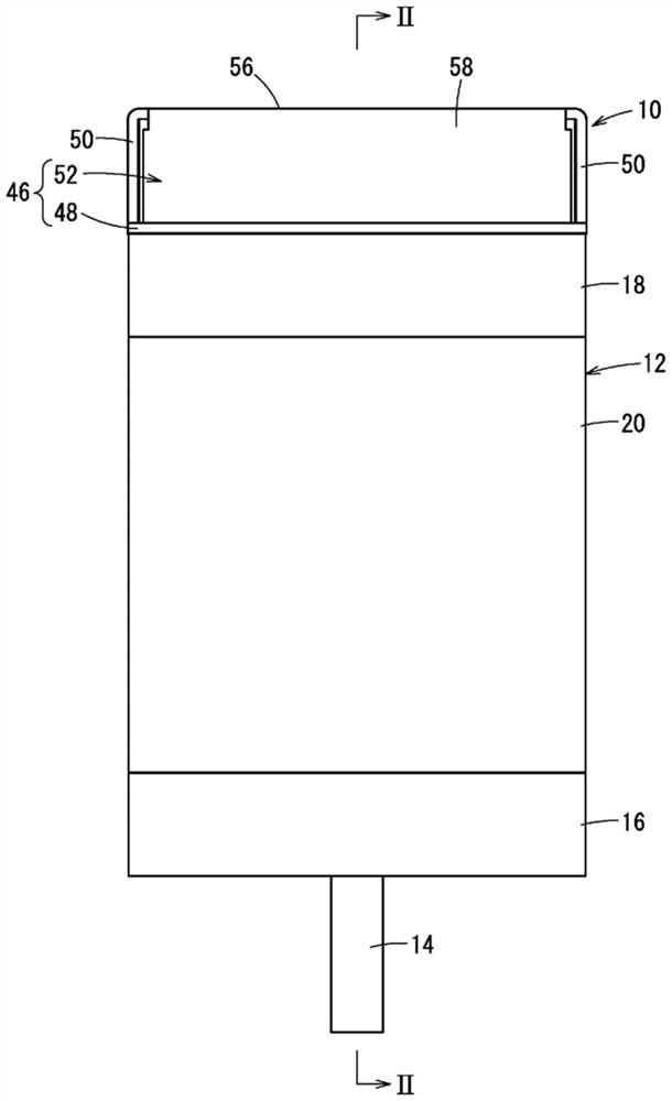
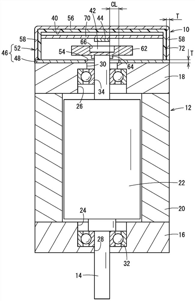
[0021] figure 1 It is a schematic whole front view of the motor 12 (rotary drive part) provided with the encoder 10 which concerns on this embodiment, figure 2 yes figure 1 The II-II line in the cross-sectional view. The encoder 10 has a function of detecting the rotation angle of the rotary shaft 14 (rotary body) of the motor 12 .

[0022] First, the motor 12 will be briefly described. The motor 12 has ...


PUM


Abstract

A magnetic encoder (10) is provided with: a first member (48) including a first wall portion in which an insertion hole (54) through which a rotating body (14) passes is formed; and a second member (52) including a second wall portion (56). A permanent magnet (42) and a magnetic sensor (44) for detecting a magnetic field change caused by the permanent magnet (42) are sandwiched between the first wall section (48) and the second wall section (56). In this structure, the first member (48) and the second member (52) are made of mild steel containing at most 3.0 wt% carbon.

Description

technical field [0001] The invention relates to a magnetic encoder for detecting the rotation angle of a rotating body. Background technique [0002] As is well known, a magnetic encoder has a permanent magnet and a magnetic sensor, and is widely used as a device for detecting the position and rotation angle of a rotating body. As described in Japanese Patent Application Laid-Open No. 2019-15536, the permanent magnet rotates with the rotation of a rotating body fixed to the rotating shaft of the motor. Due to this rotation, the magnetic field generated by the permanent magnet changes. A magnetic sensor detects this change in the magnetic field. As a result, the rotation angle (or rotation amount) of the rotation shaft is obtained. [0003] In such a configuration, when the permanent magnet or the magnetic sensor is affected by an external magnetic field, the detected value becomes a value different from the actual rotation angle. That is, the accuracy of the detection re...

Claims


Application Information

Patent Timeline
Patent Type & Authority Applications(China)
IPC IPC(8): G01D5/12
CPCG01D5/12G01D2205/50G01D5/145G01D11/245G01D5/245G01D5/20G01B7/30
Inventor 增井隆一石泽尚大
Owner SMC CORP
Why Eureka
Try Eureka