Electrical discharge machining device

A technology of electrical discharge machining and machining fluid, which is applied to electric processing equipment, metal processing equipment, circuits, etc., and can solve problems such as slow processing speed, electrode damage, and abnormal consumption

Inactive Publication Date: 2014-07-09
藤本一郎
View PDF10 Cites 0 Cited by
  • Summary
  • Abstract
  • Description
  • Claims
  • Application Information

AI Technical Summary

Problems solved by technology

In other words, when a large machining current is applied to a small machining area, damage or abnormal consumption of the electrode will occur, and when a small machining current is applied to a large machining area, the machining speed will decrease. Extremely slow, so the processing conditions are set based on the processing area

Method used


Image

  • Electrical discharge machining device
  • Electrical discharge machining device
  • Electrical discharge machining device

Examples


Embodiment 1

[0096] Below, based on Figure 1 to Figure 10 Examples of the present invention will be described.

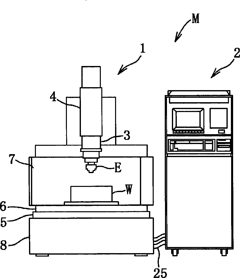
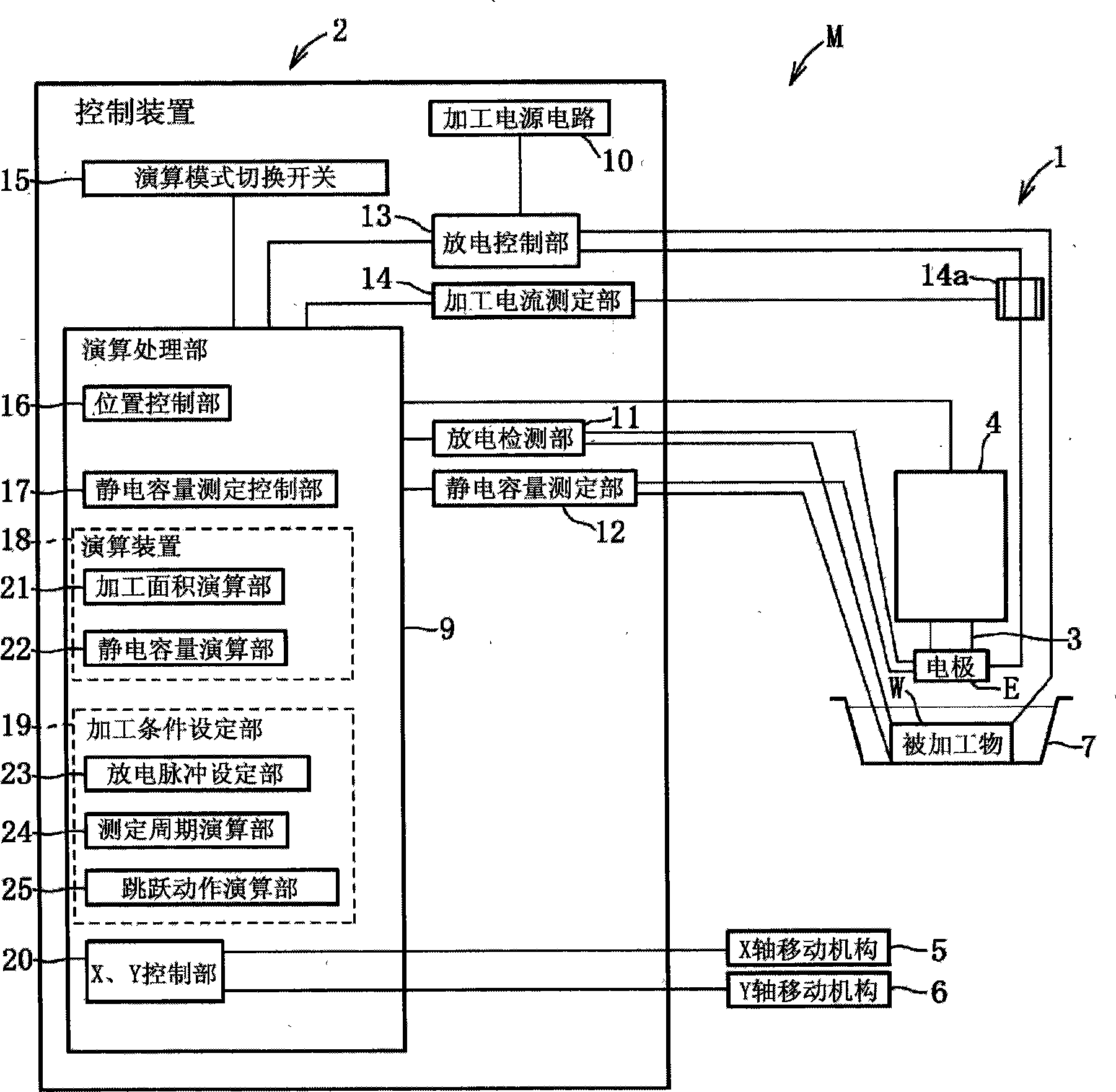
[0097] Such as figure 1 As shown, the electrical discharge machining device M is a device that supplies a machining fluid to the gap between the electrode E and the workpiece W, and applies a discharge pulse from the electrode E to the workpiece W to perform electrical discharge machining on the workpiece W. . This electrical discharge machining device M has peripheral equipment such as a machining machine body 1 , a control device 2 , and a machining liquid tank 7 . The processing machine body 1 is composed of: a head 3 equipped with an electrode E; a Z-axis moving mechanism 4 (moving device) as a feeding device that can reciprocate the head 3 in the up and down direction (Z-axis); an X-axis moving mechanism 5. The machining liquid tank 7 containing the workpiece W can be placed along the figure 1 The horizontal reciprocating movement in the left and right direction (X axi...

Embodiment 2

[0175] Second, based on Figure 11 Example 2 will be described.

[0176] The difference from Example 1 is that the distance D from the surface of the workpiece W in Example 1 to the processing surface is known, but the distance D in Example 2 is unknown.

[0177] The columnar electrode EB is brought into contact with the processing surface of the workpiece W to initialize the moving position (interpolar distance) of the electrode EB. Secondly, if Figure 11 As shown in (a), the electrode EB is moved upwards by the Z-axis moving mechanism 4 to move the electrode EB to the first moving position. At this time, if it is set as: the first total electrostatic capacity C31, the inter-electrode electrostatic capacity Cp31 between the electrode advancing end surface and the processing surface, the processing area SB, the first two-pole distance h31 from the electrode advancing end surface to the processing surface, and the side surface of the electrode EB The electrostatic capacitan...

Embodiment 3

[0195] Second, based on Figure 12 Example 3 will be described.

[0196] It differs from Example 1 in that: the distance D from the surface of the workpiece W in Example 1 to the processing surface is known, while the distance D in Example 3 is unknown and the measured distance between two poles includes an error distance alpha. In addition, the error distance α is caused by machining chips accumulated on the machining surface of the workpiece W or the backlash of the gear system of the Z-axis moving mechanism 4. When no backlash occurs, the machining debris on the machining surface The accumulation amount of is represented by a positive value, and when a backlash occurs, it represents the total value of the negative value of the backlash amount and the positive value of the accumulation amount of machining debris.

[0197] The columnar electrode EC is brought into contact with the processing surface of the workpiece W to initialize the moving position (distance between elec...


PUM


Abstract

The invention discloses an electrical discharge machining device (M), which is equipped with: a Z-axis moving mechanism (4), which can move an electrode (E) precisely; a position control unit (16), which detects the moving distance of the electrode (E); and measures electrostatic capacity Part (12) and capacitance measurement control part (17) can measure the total electrostatic capacitance between the processed part of the workpiece (W) and the electrode (E); and the processing area calculation part (21) and the electrostatic capacity calculation part (22), the processing area calculation part (21) and the electrostatic capacitance calculation part (22) are in the electric discharge machining, when the electrode (E) is moved to the first and second moving positions by the Z-axis moving mechanism (4) When using the first and second pole distances h1 and h2 detected by the position control unit (16) and the first and second totals measured by the capacitance measurement unit (12) and the capacitance measurement control unit (17) The electrostatic capacitances C1 and C2 are respectively calculated by calculating the processing area (S) of the processing surface and the first and second inter-electrode electrostatic capacitances Cp1 and Cp2 between the electrode advancing end surface and the processing surface. Therefore, based on the processing area (S) and the electrostatic capacitance Cp1 and Cp2 between the first and second electrodes, the electrical processing conditions of the discharge pulse are set, and the processing conditions are changed in the appropriate measurement period corresponding to the state between the two electrodes, and the jump is controlled. action.

Description

technical field [0001] The present invention relates to an electric discharge machining device for performing electric discharge machining on the processed surface of the workpiece facing the advancing end surface of the electrode by causing electric discharge between the electrode and the workpiece, and also relates to an electric discharge machining device capable of performing electric discharge machining with high precision. An electric discharge machining device that calculates the processing area of ​​the processing surface or the electrostatic capacitance between electrodes and the processing surface to set appropriate processing conditions. Background technique [0002] Conventionally, the workpiece is machined into the same shape as the electrode by making the electrode face the workpiece and discharging it in the inter-electrode gap between the advancing end surface of the electrode in the machining travel direction and the machining surface of the workpiece. In th...

Claims


Application Information

Patent Timeline
Patent Type & Authority Patents(China)
IPC IPC(8): B23H1/02
CPCB23H7/14B23H7/20B23H1/02B23H1/04
Inventor 藤本一郎
Owner 藤本一郎
Why Eureka
Try Eureka