
Blanking device for pressure sensor diaphragm production

A pressure sensor and blanking technology, applied in the field of blanking devices, can solve the problems of large stainless steel plates, small sizes, unqualified diaphragms, etc.

Pending Publication Date: 2022-03-22
西安西灵传感技术有限公司
View PDF10 Cites 0 Cited by
  • Summary
  • Abstract
  • Description
  • Claims
  • Application Information

AI Technical Summary

Problems solved by technology

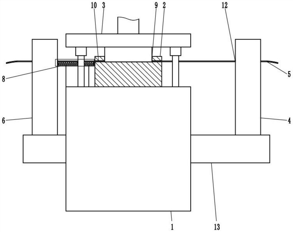
[0004] However, because the diaphragm in the pressure sensor is generally thinner and smaller in size, the stainless steel plate is mostly a narrow and long thin strip. Manually holding it by hand can ensure that the unprocessed steel at the rear end is approximately the same as the working surface of the punching table. Keep the same height, but there is no constraint on the processed waste end. Since the stainless steel plate is mostly narrow and long thin strips, the curvature of the stainless steel plate will become larger and larger with the extension of the waste end, so that it is located on the punching table. The curvature of the stainless steel plate in the section to be processed is relatively large, so that the processed diaphragm may appear wavy embossed during punching, resulting in the diaphragm being unqualified

Method used


Image

  • Blanking device for pressure sensor diaphragm production
  • Blanking device for pressure sensor diaphragm production
  • Blanking device for pressure sensor diaphragm production

Examples


Embodiment Construction

[0040] A specific embodiment of the present invention will be described in detail below in conjunction with the accompanying drawings, but it should be understood that the protection scope of the present invention is not limited by the specific embodiment.

[0041] In describing the present invention, it should be understood that the terms "center", "longitudinal", "transverse", "length", "width", "thickness", "upper", "lower", "front", " Rear", "Left", "Right", "Vertical", "Horizontal", "Top", "Bottom", "Inner", "Outer", "Axial", "Radial", "Circumferential" The orientation or positional relationship indicated by etc. is based on the orientation or positional relationship shown in the drawings, and is only for the convenience of describing the technical solution of the present invention and simplifying the description, rather than indicating or implying that the referred device or element must have a specific orientation, Constructed and operative in a particular orientation a...


PUM


Abstract

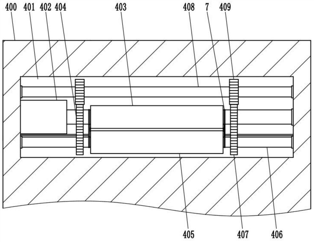
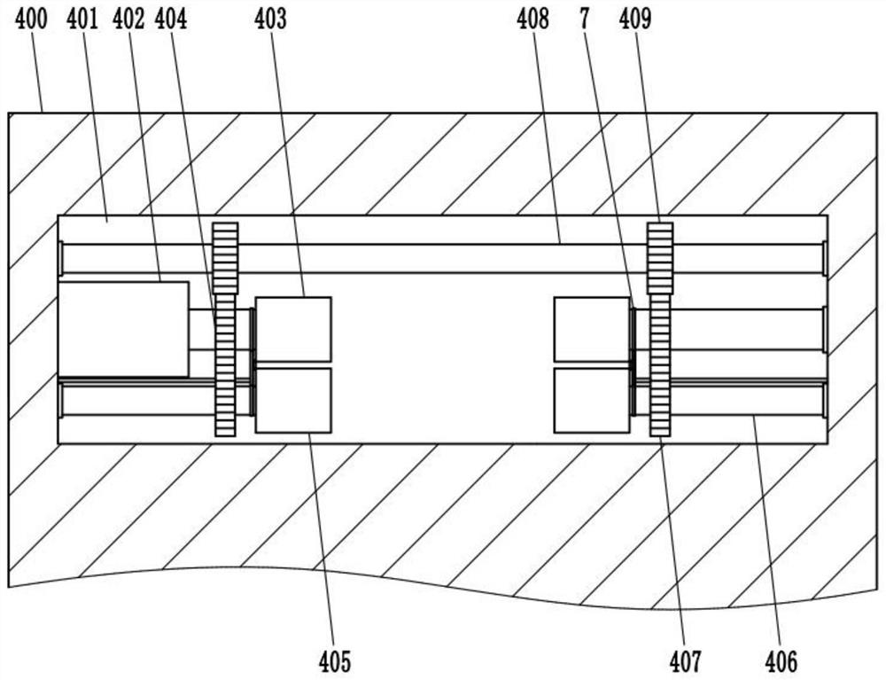
The invention relates to the technical field of blanking devices, and discloses a blanking device for pressure sensor diaphragm production, which comprises a base, a punching table, a blanking mechanism, a feeding mechanism and a traction mechanism, the punching table is fixed on the base, the blanking mechanism is positioned above the punching table and is connected with the base, the feeding mechanism is fixed on the base and is positioned on one side of the feeding end of the punching table, and the traction mechanism is connected with the feeding mechanism. The feeding mechanism is used for conveying plates to the punching table, the conveying end of the feeding mechanism is flush with the working face of the punching table, the traction mechanism is fixed to the base and located on one side of the discharging end of the punching table, the traction mechanism draws the plates punched by the punching mechanism, and the traction end of the traction mechanism is flush with the working face of the punching table. According to the blanking device for pressure sensor diaphragm production, it can be guaranteed that a stainless steel plate is kept at the same horizontal height on the working face of the punching table and in front of and behind the stainless steel plate, and the situation that due to the fact that the curvature of the stainless steel plate is too large, wave-shaped embossing appears on a machined diaphragm is avoided.

Description

technical field [0001] The invention relates to the technical field of punching devices, in particular to a punching device for pressure sensor diaphragm production. Background technique [0002] A pressure transducer (Pressure Transducer) is a device or device that can sense a pressure signal and convert the pressure signal into an available output electrical signal according to a certain rule. The pressure sensor is usually composed of a pressure sensitive element and a signal processing unit. The diaphragm is an important part of the pressure sensor. The pressure-sensitive diaphragm of the pressure sensor is divided into a ceramic diaphragm and a stainless steel diaphragm. The processing of the stainless steel diaphragm needs to be processed into a size that meets the size by a punching device. [0003] The basic structure of the punching device for pressure sensor diaphragm production mainly includes: base, punching table and punching mechanism. The stainless steel plate...

Claims


Application Information

Patent Timeline
Patent Type & Authority Applications(China)
IPC IPC(8): B21D28/00B21D28/04B21D43/09B21D43/02
CPCB21D28/00B21D28/04B21D43/09B21D43/027
Inventor 李继文李碧芯
Owner 西安西灵传感技术有限公司
Learn More