

Sleeve-type superfine diameter osteofixation needle
A fixed needle and cannula-type technology, applied in medical science, veterinary equipment, veterinary surgery, etc., can solve the problems of large surgical trauma, limited wide application, expensive, etc., and achieve a wide range of indications and strong operability Effect
- Summary
- Abstract
- Description
- Claims
- Application Information
AI Technical Summary
Problems solved by technology
Method used
Image

Examples
Embodiment 1
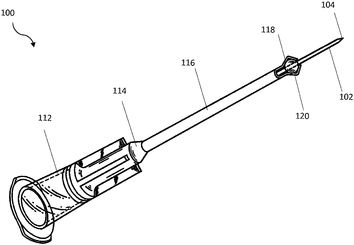
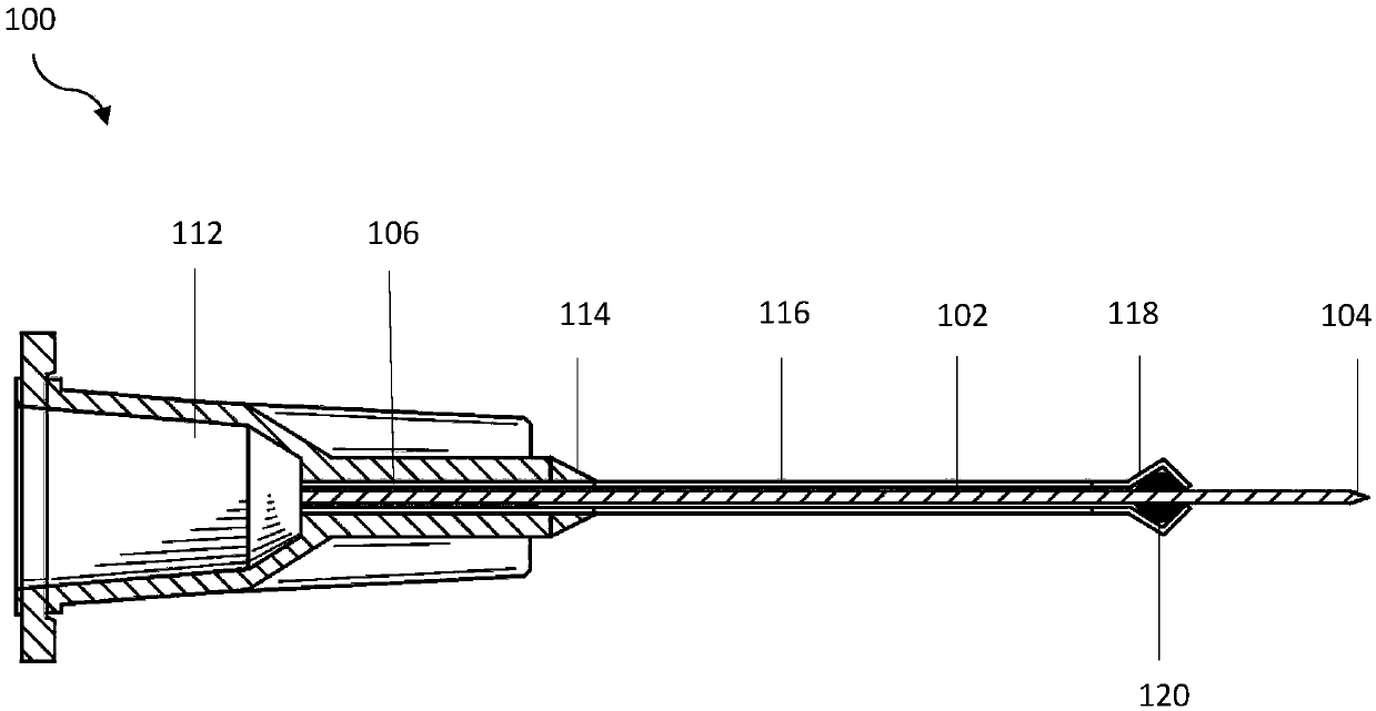
[0083] Such as Figure 1-7D The illustrated sleeve-type ultra-thin bone fixation pin 100 includes a booster sleeve 116 and an ultra-thin bone fixation pin 102 built in the booster sleeve. The bone fixation pin 102 is 0.3mm in diameter.
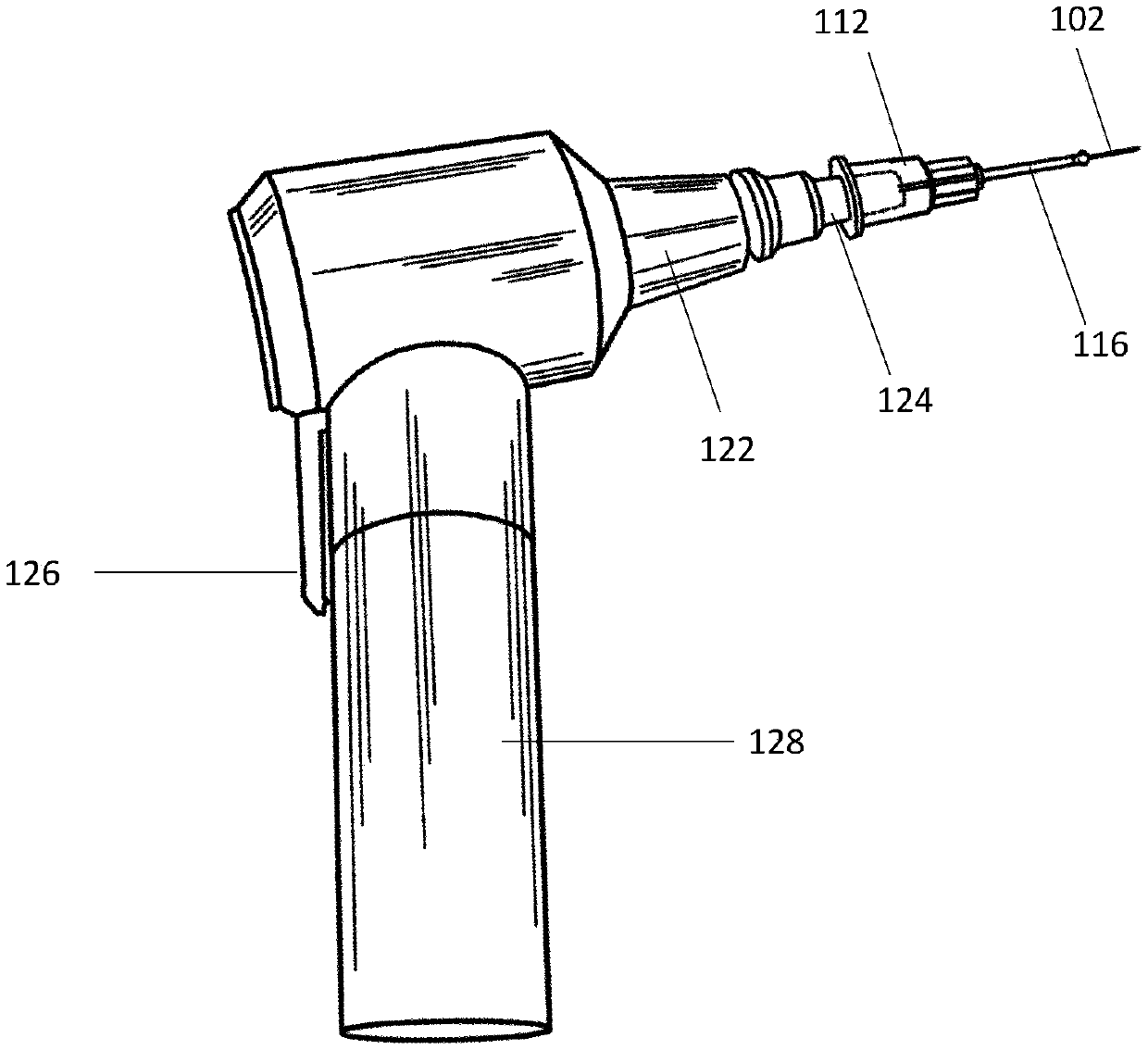
[0084] One end of the booster sleeve 116 is provided with an adapter seat 112 connected with the rotor adapter head 124 of the driving motor 122 . The bone fixation pin 102 is loaded in the booster sleeve 116, and is rigidly connected by the clamping arm 118 at the distal end of the booster sleeve 116 and the detachable rigid plastic ball 120; the clamping arm 118 and the detachable rigid plastic ball 120 bind the bone The fixation needle 102 and the booster sleeve 116 are rigidly integrated, and the length of the pin tip of the bone fixation pin 102 extending out of the booster sleeve 116 is locked to 6 mm, so as to ensure that the protruding needle tip has sufficient mechanical strength to meet the requirements of percutaneous electrokineti...
Embodiment 2
[0093] Such as Figure 8-1 The type II cannula type ultra-thin bone fixation needle shown in 0 includes a type II needle sleeve 214 and a built-in type II needle 202 . Type II needle 202 has a diameter of 0.5 mm.
[0094] Such as Figure 8 , 9A , 9B, one end of the type II needle sleeve 214 is provided with a type II needle adapter seat 212 connected to the rotor of the drive motor, the type II needle adapter seat is in the shape of a hexagonal prism, and is compatible with the type II needle adapter cavity 210 of the cordless motor match. The type II needle 202 is loaded in the type II needle cannula 214, and is rigidly connected by the cannula tightening thread 216 at the distal end of the type II needle cannula 214 and the cannula tightening nut 218.
[0095] Such as Figure 10A , 10B As shown in , 10C and 10D, the distal port of the type II needle cannula 214 is divided into three equal parts, and extended as trapezoidal flaps, and the casing tightening threads 216 a...
Embodiment 3
[0097] This example is used to explain the application method and process of the cannula-type ultra-thin bone fixation needle of the present invention in external fixation of mouse tibia.
[0098] Such as Figure 11-30 Shown is a schematic diagram of establishing a mouse tibia-femoral external fixator model using the sleeve type ultra-fine bone fixation needle of the present invention.
[0099] Such as Figure 11 As shown, the mouse is fixed in the orthopedic surgery fixation device 300, the hind limb of the mouse is placed in a standard position in front of the animal orthopedic surgery positioning fixture 302, and a positioning needle hole 304 that can be positioned through the anatomical position popliteal fossa is shown.
[0100] Such as Figure 12 As shown, the mouse hindlimb is positioned on the animal bone surgical fixation device, and is positioned through the anatomical position of the popliteal fossa by a 25G syringe needle as a positioning pin 306 passing through ...
PUM
| Property | Measurement | Unit |
|---|---|---|
| Diameter | aaaaa | aaaaa |
Abstract
Description
Claims
Application Information