Metal defect detection method of laser-electromagnetic ultrasonic nondestructive testing system

An electromagnetic ultrasonic and non-destructive testing technology, applied in the analysis of solids using sonic/ultrasonic/infrasonic waves, etc., can solve problems such as large amplitude, and achieve the effects of simple equipment, good repeatability and high measurement accuracy

Active Publication Date: 2012-11-28
山东山科光电技术与装备研究院有限公司
View PDF4 Cites 20 Cited by
  • Summary
  • Abstract
  • Description
  • Claims
  • Application Information

AI Technical Summary

Problems solved by technology

It should overcome the shortcomings that the existing non-contact laser ultrasonic diffraction method is difficult to apply to the detection of rough surface materials, and because the el

Method used


Image

  • Metal defect detection method of laser-electromagnetic ultrasonic nondestructive testing system
  • Metal defect detection method of laser-electromagnetic ultrasonic nondestructive testing system
  • Metal defect detection method of laser-electromagnetic ultrasonic nondestructive testing system

Examples


Example Embodiment

[0029] Example 1: The specific implementation of metal material surface defect detection is:

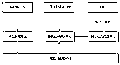
[0030] figure 1 It is a schematic diagram of a laser-electromagnetic ultrasonic nondestructive testing system. First, the pulse laser, the three-dimensional mechanical stepping device, the transverse wave electromagnetic ultrasonic sensor, the signal amplifying and filtering unit, the digital oscilloscope and the computer are electrically connected in sequence, and the electromagnetic ultrasonic receiving unit is fixed to the three-dimensional mechanical stepping device. Calibrate the pulse laser and the linear focus unit position so that they are placed in the same center. Adjust the position of the cylindrical lens in the linear focusing unit so that the distance between the 45 gauge steel and the cylindrical lens is 200 mm.
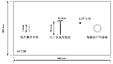
[0031] figure 2 A schematic diagram of surface crack production of artificial wounds in No. 45 steel is given. The size of No. 45 steel is 400 mm×600 mm×60 mm. ...

Example Embodiment

[0034] Example 2: The specific implementation of the detection of internal defects of metal materials is as follows:

[0035] Figure 5 A schematic diagram of making artificial wound holes in No. 45 steel is given. The size of No. 45 steel is 900 mm × 200 mm×300 mm. The hole type artificial wound is processed by a drilling and milling center 60 mm from the upper surface of No. 45 steel. The dimensions are 7 mm×30 mm, 5 mm×30 mm and 3 mm×30 mm in order. The test results of 3 mm×30 mm holes are given in the examples. The output energy of the calibrated pulse laser is 150 m J / pulse. Adjust the position of the cylindrical lens in the linear focusing unit so that the two are placed at the same center, and meet the requirement of the 45 gauge steel surface to be tested in the cylindrical lens of the linear focusing unit. Focal length. Turn on the working power of the transverse wave electromagnetic ultrasonic sensor and the 3D mechanical stepping motor, and adjust the distance between...


PUM

PropertyMeasurementUnit
Pulse widthaaaaaaaaaa
Wavelengthaaaaaaaaaa
Snraaaaaaaaaa

Abstract

The invention relates to a metal defect detection method of a laser-electromagnetic ultrasonic nondestructive testing system. The method adopts the laser-electromagnetic ultrasonic testing system composed of a pulsed laser, a linear focusing unit, a transverse wave electromagnetic ultrasonic sensor, a three-dimensional mechanical stepping device, a signal amplification filtering system, a digital oscilloscope and a computer. The system is utilized to excite a Gaussian laser pulse, which is then delivered to the surface of a metal material through an optical focusing system, and at the same time surface waves as well as transverse waves are excited. The transverse wave electromagnetic ultrasonic sensor is used for receiving, and on the basis, positioning detection of the surface and near surface defects can be performed. The method makes use of the transverse wave electromagnetic ultrasonic sensor to receive diffraction transverse waves generated when the transverse waves encounter an internal defect, and when the sensor is position right above a metal material internal defect, the received diffraction transverse wave signal has the strongest amplitude, so that the horizontal position of the defect can be determined, and the vertical position of the defect can be determined by the defect echo time. The method can realize detection of metal material surface, near surface and internal defects at the same time.

Description

technical field [0001] The invention relates to a metal defect detection method of a laser-electromagnetic ultrasonic nondestructive testing system, belonging to the field of ultrasonic nondestructive testing and evaluation. Background technique [0002] So far, no practical method of non-contact ultrasonic diffraction detection based on laser-electromagnetic ultrasonic technology that can be applied to metal material defects has been seen. The ultrasonic diffraction method has the advantages of high detection accuracy and fast speed when detecting material defects. At present, since most ultrasonic diffraction methods used to detect internal defects of materials are based on contact piezoelectric ultrasonic technology, the detection sensitivity is greatly affected by the coupling state. In the article "Time-of-Flight Diffraction Measurement Using Laser Ultrasound", Mihara proposed that laser can be used to excite ultrasonic waves and combined with laser interferometer to r...

Claims


Application Information

Patent Timeline
IPC IPC(8): G01N29/04
Inventor 赵扬贾中青马健宋江峰郭锐刘帅孙继华翟瑞占
Owner 山东山科光电技术与装备研究院有限公司
Why Eureka
Try Eureka