
Hollow bias structure of wrist of industrial robot

A technology of industrial robots and offset structures, applied in manipulators, manufacturing tools, joints, etc., can solve problems such as production safety hazards, increase cycle time, and difficulty in improving spraying efficiency, so as to improve bearing capacity, reduce structural weight, and work efficiency Improved effect

Active Publication Date: 2015-12-16
希美埃(芜湖)机器人技术有限公司
View PDF8 Cites 10 Cited by
  • Summary
  • Abstract
  • Description
  • Claims
  • Application Information

AI Technical Summary

Problems solved by technology

The traditional robot wrist adopts a double-supported wrist structure, which limits the range of movement of the 5-axis to a large extent. The movements that can be realized only by moving the 5-axis must be realized by moving other axes. This kind of driving structure undoubtedly increases the takt time of the process in actual production, and cannot meet the complex curved surface spraying needs in a narrow space, and it is difficult to improve the spraying efficiency
In addition, due to the special environmental restrictions of painting, all paint pipes, solution pipes, air pipes, and other cables need to pass through the inside of the robot and be directly connected to the end effectors of the robot (such as spray guns, high-speed rotary cups) to use In order to ensure the cleanliness of the robot, and this wiring method is easy to maintain, avoiding the pipeline hanging outside the robot arm, which will cause hidden dangers to production safety. The traditional double-supported wrist structure cannot effectively wrap the cables and pipelines, and it is difficult to protect them. effect

Method used


Image

  • Hollow bias structure of wrist of industrial robot
  • Hollow bias structure of wrist of industrial robot
  • Hollow bias structure of wrist of industrial robot

Examples


Embodiment Construction

[0037] In order to make the technical means and creative features realized by the present invention easy to understand, the present invention will be further elaborated below.

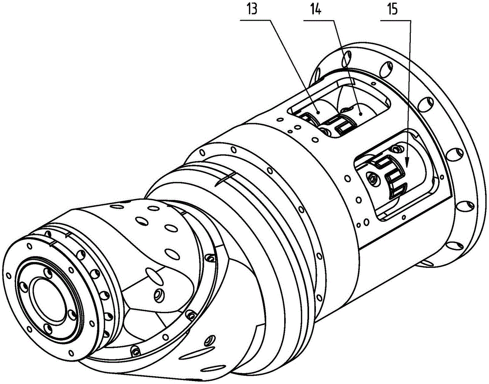
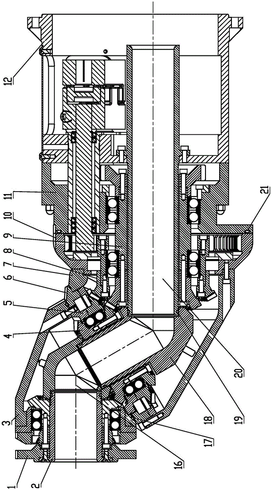
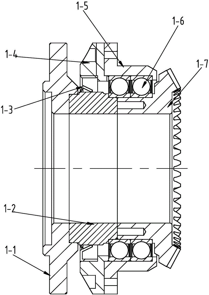
[0038] Such as Figure 1 to Figure 2 As shown, a hollow offset structure of the wrist of an industrial robot, including the terminal output assembly 1, the first internal sheath 2, the 6-axis wrist body 3, the first 6-axis transition transmission assembly 4, the 5-axis output assembly 5, and the 5-axis Cross roller bearing locking flange 6, 4-axis wrist body 7, 5-axis transition transmission assembly 8, No. 2 6-axis transition transmission assembly 9, 4-axis output assembly 10, No. 1 wrist joint 11, No. 2 wrist joint 12, 4-axis input assembly 13, 5-axis input assembly 15, 6-axis input assembly 14, No. 2 inner sheath 16, No. 1 O-ring 17, No. 3 inner sheath 18, No. 1 O-ring 19, No. 4 inner sheath 20, No. 2 O-shaped sealing ring 21.

[0039]The No. 2 6-axis transition transmission assembly 9 is set on t...


PUM


Abstract

The invention relates to a hollow bias structure of a wrist of an industrial robot. The hollow bias structure comprises a tail end output assembly, a first inner sheath, a sixth-axis wrist body, a first sixth-axis transition transmission assembly, a fifth-axis output assembly, a fifth-axis crossed roller bearing locking flange, a fourth-axis wrist body, a fifth-axis transition transmission assembly, a second sixth-axis transition transmission assembly, a fourth-axis output assembly, a first wrist connecting piece, a second wrist connecting piece, a fourth-axis input assembly, a fifth-axis input assembly, a sixth-axis input assembly, a second inner sheath, a first O-type sealing ring, a third inner sheath, a first O-type sealing ring, a fourth inner sheath and a second O-type sealing ring. The left side of the fourth inner sheath is sleeved with the second sixth-axis transition transmission assembly, and the right side of the fourth inner sheath is sleeved with the second wrist connecting piece. A servo motor is used for controlling, the wrist is driven to run through a speed reducer and a series of transmission manners, a fifth axis can rotate without limitations, the takt can be increased, efficiency can be improved, and the requirements of the spraying technology can be met.

Description

technical field [0001] The invention relates to the technical field of industrial robot wrist structures, in particular to a hollow offset structure for industrial robot wrists. Background technique [0002] The structure of the industrial robot body plays a key role in the performance of the robot. For some special industries, such as the spraying industry, the robot wrist is required to be flexible and strong, and be able to complete the spraying operations on complex curved surfaces and narrow spaces. The traditional robot wrist adopts a double-supported wrist structure, which limits the range of movement of the 5-axis to a large extent. The movements that can be realized only by moving the 5-axis must be realized by moving other axes. This kind of driving structure undoubtedly increases the takt time of the process in actual production, and cannot meet the complex curved surface spraying needs in a narrow space, and it is difficult to improve the spraying efficiency. In...

Claims


Application Information

Patent Timeline
Patent Type & Authority Applications(China)
IPC IPC(8): B25J17/00
CPCB25J17/00
Inventor 塞尔乔·德拉·梅亚马可·扎诺尔米凯拉·比亚索尼
Owner 希美埃(芜湖)机器人技术有限公司
Learn More