Exposure unit

A technology of exposure device and exposure surface, which is applied in the direction of photolithography exposure device, microlithography exposure equipment, optics, etc., can solve problems such as easy accumulation of dust and poor exposure, and improve image resolution, high quality and productivity Effect

Active Publication Date: 2005-11-30
SANEI GIKEN
View PDF0 Cites 10 Cited by
  • Summary
  • Abstract
  • Description
  • Claims
  • Application Information

AI Technical Summary

Problems solved by technology

When the exposure surface of the tape-shaped substrate is directly exposed with dust attached, it is easy to cause exposure failure
In addition, dust falling from the tape-shaped substrate tends to accumulate on the photomask and the reflector of the light source arranged under the tape-shaped substrate.
This accumulated dust will become the main cause of many poorly exposed products

Method used


Image

  • Exposure unit
  • Exposure unit

Examples


Embodiment Construction

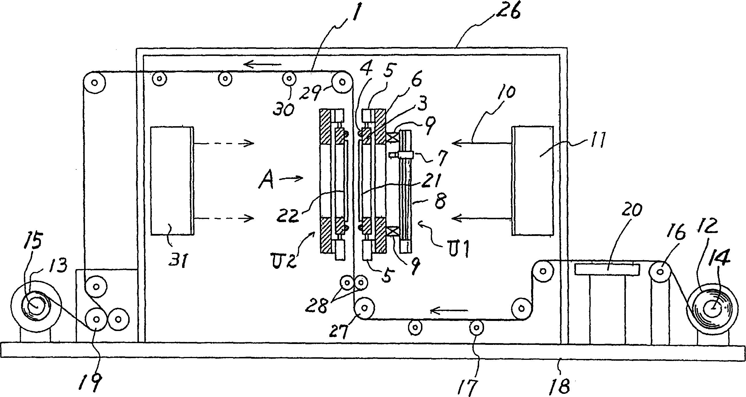
[0027] figure 1 It is a schematic vertical cross-sectional view showing an example of the exposure apparatus of the present invention. The exposure device includes: a base 18 and a frame 26 disposed on the base 18 . On the right end portion of the base 18, the reel 14 for drawing out is provided. The flexible tape-shaped substrate 1 is wound into a cylinder 12 on the reel 14 for extraction. On the other hand, a winding reel 15 is provided at the left end portion of the base 18 .

[0028] A conveying drive roller 19 is provided between the unwinding reel 14 and the winding reel 15 . The conveyance drive roller 19 intermittently draws out the strip-shaped substrate 1 wound on the take-out reel 14 every predetermined length. The strip-shaped substrate 1 drawn out from the drawing reel 14 enters a vertical path through guide rollers 16, 17, 27, 28, and becomes a vertical state. The region where the strip substrate 1 is in a vertical state is an exposed portion. In the vertic...


PUM


Abstract

The objective of the invention is to provide products of uniform quality, by eliminating harmful effects by the sagging of a belt-like substrate by self weight in exposure and aligning the belt-like substrate and photomasks to high dimensional accuracy. In an exposure device, a belt-like substrate 1 is exposed for each predetermined length region while intermittently sending the belt-like substrate 1 along its longitudinal direction. The flexible belt-like substrate 1 having sensitive material stuck surfaces to be exposed is moved by a drive unit 19 between a feeding reel 14 and a take-up reel 15. A vertical path, in which the belt-like substrate 1 becomes a vertical state is formed between the feeding reel 14 and the take-up reel 15. An exposure section is located in the vertical path. The exposure section has photomasks 21, 22. Patterns drawn in the photomasks 21, 22 are transferred to the surfaces of the belt-like substrate 1 to be exposed by the lights from light sources.

Description

technical field [0001] The invention relates to an exposure device for irradiating light on a substrate through a photomask to transfer patterns drawn on the photomask to the substrate, in particular to a flexible belt-shaped substrate attached with a photosensitive material. Exposure equipment for substrate exposure. Background technique [0002] There is known an exposure device that is arranged along a strip-shaped substrate between a reel for pulling out a flexible strip-shaped substrate into a cylinder and a reel for winding the strip-shaped substrate into a cylinder. The tape-shaped substrate is intermittently fed in the longitudinal direction of the substrate, and the tape-shaped substrate is exposed at predetermined length regions. An exposure surface to which a photosensitive material is attached is formed on at least one surface of the tape-shaped substrate. The exposure surface is irradiated with light through the photomask, and a pattern such as a circuit drawn...

Claims


Application Information

Patent Timeline
Patent Type & Authority Applications(China)
IPC IPC(8): G03F7/20H05K3/06
CPCG03F7/7035G03F9/7038
Inventor 三宅健今西贤
Owner SANEI GIKEN
Why Eureka
Try Eureka