A multi-high-energy beam-enhanced in situ method for measuring vapor recoil pressure in additive manufacturing

A technology of additive manufacturing and measurement methods, which is applied in the directions of measuring fluid pressure, processing and manufacturing, and additive manufacturing. It can solve problems such as low measurement efficiency, small quantity, and restrictions on in-depth research on steam recoil behavior, so as to achieve easy capture and improve efficiency. Effect

Active Publication Date: 2022-05-13
TSC LASER TECH DEV BEIJING CO LTD +1
View PDF8 Cites 0 Cited by
  • Summary
  • Abstract
  • Description
  • Claims
  • Application Information

AI Technical Summary

Problems solved by technology

However, during the interaction between a single high-energy beam and the powder material, most of the spatter exits backward (the horizontal component of its velocity is opposite to the moving direction of the high-energy beam), and a small number of splashes exit forward (the horizontal component of its velocity is in the same direction as the high-energy beam), However, the number of typical splashes whose motion state changes after being irradiated by high-energy beams among these forward-exiting spatters is even less, less than 5%.
Therefore, the small number of typical spatters and low measurement efficiency of the photoinduced vapor recoil effect obtained by the above method seriously restrict the in-depth study of the vapor recoil behavior during the high-energy beam-material interaction process.

Method used


Image

  • A multi-high-energy beam-enhanced in situ method for measuring vapor recoil pressure in additive manufacturing
  • A multi-high-energy beam-enhanced in situ method for measuring vapor recoil pressure in additive manufacturing
  • A multi-high-energy beam-enhanced in situ method for measuring vapor recoil pressure in additive manufacturing

Examples


Embodiment 1

[0056] In this example, gas-atomized GH4169 alloy spherical powder is used, and the particle size range of which is measured by Mastersizer 3000 is D10=21.7 μm, D50=31.1 μm, D90=45.0 μm. The chemical composition of the GH4169 superalloy powder is shown in Table 1.

[0057] Table 1 Chemical composition of GH4169 superalloy powder used in the experiment

[0058] Al Ti Cr Mn Fe Mo Nb C Ni 0.56 1.01 18.94 0.01 18.23 3.0 4.98 0.04 Bal.

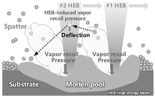
[0059] Taking the typical backward deflected splash particles under dual high-energy beams as the object, the related vapor back ramming behaviors are studied as follows:

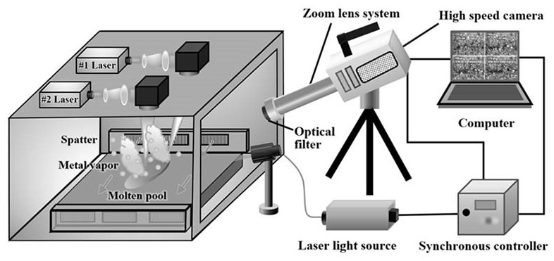
[0060] using as figure 2 For the measurement system shown, set the two laser beams at the same laser power (500W) and the same scanning speed (1000mm·s -1 ) and the same spot size (130 μm) run forward and backward on the powder bed. The #1 laser is defined as the front row laser, the #2 laser is the rear row laser, and the #2 laser is...

Embodiment 2

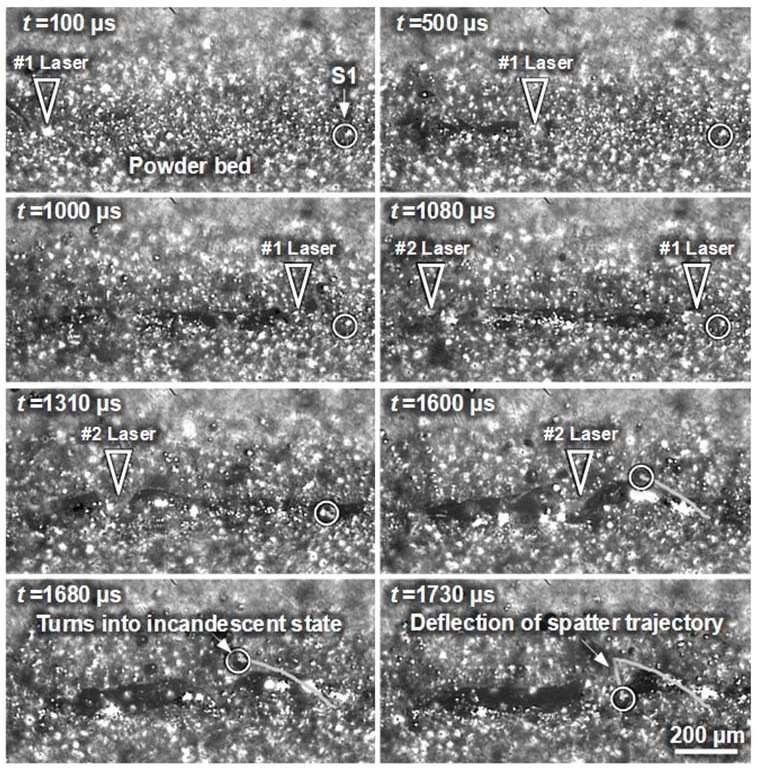
[0070] like Figure 5 Shown is the deflection diagram of the motion trajectory of the upper surface of the splash S2 under the action of photo-induced vapor recoil (high-speed imaging timing diagram). Splash S2 is emitted under the action of #1 laser vapor entrainment, at t =1350μs is captured by the backward #2 laser, causing its temperature to rise sharply, reaching the boiling point T b , the upper part of the splash particles begins to vaporize. like Image 6 As shown, the resulting metal vapor exerts a downward recoil pressure on the particles, resulting in drastic changes in their trajectory. exist t=1350μs~1370μs in a very short time, the exit angle of the sputter S2 changes from 162.2° to -96.5° (the negative sign means vertical downward), the vertical component of the exit velocity u v from 0.9m s -1 Change to -11.4m s -1 . The acceleration of the particle can be calculated by taking the derivation of the velocity-angle-time curve of motion a p . At the t...

Embodiment 3

[0072] like Figure 7 Shown is the deflection diagram of the motion trajectory of the upper surface of the splash S3 under the action of photo-induced vapor recoil (high-speed camera timing diagram). Splash S3 emerges under the action of #1 laser vapor entrainment, at t =1740μs was captured by the backward #2 laser, causing its temperature to rise sharply, reaching the boiling point T b , the upper part of the splash particles begins to vaporize. like Figure 8 As shown, the resulting metal vapor exerts a downward recoil pressure on the particles, resulting in drastic changes in their trajectory. exist t =1740μs~1760μs in a very short time, the exit angle of the sputter S3 changes from 180° to -107.4° (the negative sign means vertical downward), the vertical component of the exit velocity u v From about 0m s -1 Change to -6.2m s -1 . The acceleration of the particle can be calculated by taking the derivation of the velocity-angle-time curve of motion a p . At the ...


PUM

PropertyMeasurementUnit
particle diameteraaaaaaaaaa
radiusaaaaaaaaaa

Abstract

The invention provides a method for in-situ measurement of vapor recoil pressure in additive manufacturing with multi-high energy beam enhancement. The splashed particles in the high-energy beam additive manufacturing are used as in-situ tracer particles, dual high-energy beams are used, and the scanning mode of the dual high-energy beams is set to go forward and backward at the same time, and the backward emission generated when the "forefront high-energy beam" interacts with the powder Sputtering, after being irradiated by the "rear row of high-energy beams", deflects like an L-shape, effectively increasing the number of typical splashes under the action of photovapor recoil pressure, making it easier for high-temporal-resolution camera devices to capture the trajectory of typical splashing particles, and further Through mechanical analysis and mathematical calculation, the vapor recoil pressure during the interaction between the high-energy beam and the material is obtained, which greatly improves the efficiency of in-situ measurement of the vapor recoil pressure, and can more deeply reveal the inner law of the vapor recoil behavior in the high-energy beam additive manufacturing process.

Description

technical field [0001] The invention relates to the technical field of high-energy beam additive manufacturing and forming processing, in particular to a method for multi-high-energy beam enhanced in-situ measurement of vapor back stamping in additive manufacturing. Background technique [0002] The physical essence of laser / ion beam / electron beam additive manufacturing is the interaction of high-energy beams with materials, and it has very broad application prospects in the fields of aerospace, energy, biology, transportation and jewelry. During the interaction between the high-energy beam and the material (including non-metals such as ceramics and polymers, or metals such as stainless steel, titanium alloy, aluminum alloy, etc.), the temperature rises rapidly, and the melting point of the material is reached to melt to form a molten pool, and the boiling point of the material is vaporized. Under the action of high-energy beam, the violent vaporization of the molten pool su...

Claims


Application Information

Patent Timeline
Patent Type & Authority Patents(China)
IPC IPC(8): G01L11/00G01N15/00G01N21/85G01M9/06B22F10/28B22F10/80B33Y50/00B29C64/153B33Y10/00
CPCG01L11/00G01N15/00G01N21/85G01M9/06B22F10/28B22F10/80B33Y50/00B29C64/153B33Y10/00Y02P10/25
Inventor 殷杰郝亮尹作为李妍李正孙庆磊石斌
Owner TSC LASER TECH DEV BEIJING CO LTD
Why Eureka
Try Eureka