Turbine blade crack nondestructive testing device

A turbine blade, non-destructive testing technology, applied in the direction of measuring devices, using sound waves/ultrasonic waves/infrasonic waves to analyze solids, using sound waves/ultrasonic waves/infrasonic waves for material analysis, etc., can solve the huge workload brought by turbine blade detection, turbine The non-destructive testing of blades has a large workload, and the magnetostrictive tape cannot be reused, etc., so as to achieve the effect of rich types of testing, reducing the required time, and reducing the time

Pending Publication Date: 2022-03-22
JIANGSU FRONTIER ELECTRIC TECH
View PDF4 Cites 0 Cited by
  • Summary
  • Abstract
  • Description
  • Claims
  • Application Information

AI Technical Summary

Problems solved by technology

[0002] Before the turbine blade detection probe is used, it is necessary to bond the magnetostrictive tape to the tip of the turbine blade. In the case of the detection of the turbine blade, it is often to detect a group of turbine blades, so that the bonding resigns the work of the telescopic tape. The amount is huge, and the dismantling of the strip also brings a huge workload to the detection of turbine blades, which makes the bonding method have certain disadvantages in the detection and protection of blades
[0003] Due to the special curve of the turbine blades, the magnetostrictive strips are often fixed by bonding, which is a hard link, and the bonded magnetostrictive strips cannot be reused. The detection of turbine blades is often a group of turbine blades. blade, rather than a turbine blade, making the NDT workload of turbine blades huge

Method used


Image

  • Turbine blade crack nondestructive testing device
  • Turbine blade crack nondestructive testing device
  • Turbine blade crack nondestructive testing device

Examples


Embodiment Construction

[0023] The specific implementation manners of the present invention will be described in further detail below in conjunction with the accompanying drawings.

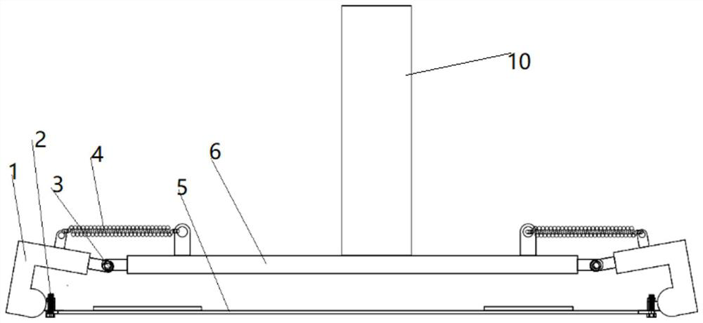
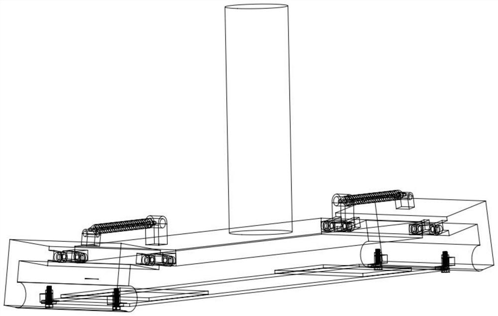
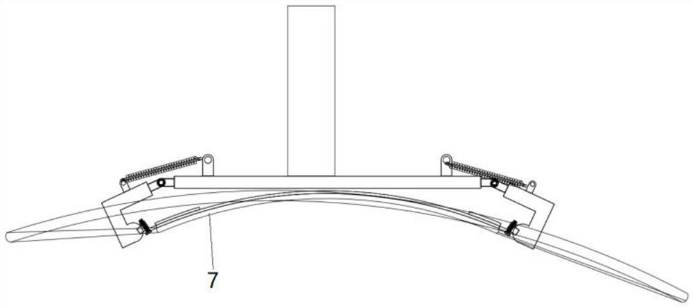
[0024] Such as Figure 1-3 As shown, the probe device of the present invention is arranged symmetrically as a whole, including a blade magnetostrictive non-destructive testing splint 1, a support device 6, a tension spring 4, a connecting bolt 2, a living hinge 3 and a composite probe 5; the two sides of the support device 6 respectively pass through The corresponding living hinge 3 is movably connected with the two splints 1, so that the splint has a certain degree of freedom, which can be changed with the width of the fixed turbine blade, increasing the type of detection blade pairs, and also adapting to the curvature of different turbine blades, so that The composite probe can be attached more closely to the turbine blades to inspect the turbine blades more strictly. Both sides of the support device 6 are also flexib...


PUM


Abstract

The invention discloses a nondestructive testing device for cracks of turbine blades. The device is integrally and symmetrically arranged and comprises a clamping plate, a supporting device, a tension spring, a connecting bolt, a movable hinge and a composite probe, the two sides of the supporting device are movably connected with the two clamping plates through corresponding movable hinges respectively, the two sides of the supporting device are further movably connected with the two clamping plates through corresponding tension springs respectively, a composite probe is arranged below the supporting device, and the two sides of the composite probe are movably connected with the two clamping plates through corresponding connecting bolts respectively; the turbine blade is placed on the lower surface of the composite probe, the supporting device presses downwards, the relative positions of the clamping plate, the supporting device and the composite probe change, the composite probe elastically deforms, the lower surface of the composite probe is tightly attached to the surface of the turbine blade, and nondestructive testing on the surface of the turbine blade is achieved through operation of the composite probe. The nondestructive testing efficiency of the turbine blade is improved, and the method has certain engineering significance.

Description

technical field [0001] The invention relates to a blade nondestructive detection device in the field of blade detection, in particular to a turbine blade crack nondestructive detection device. Background technique [0002] Before the turbine blade detection probe is used, it is necessary to bond the magnetostrictive tape to the tip of the turbine blade. In the case of the detection of the turbine blade, it is often to detect a group of turbine blades, so that the bonding resigns the work of the telescopic tape. The amount is huge, and the dismantling of the strip also brings a huge workload to the inspection of turbine blades, which makes the bonding method have certain shortcomings in the detection and protection of blades. [0003] Due to the special curve of the turbine blades, the magnetostrictive strips are often fixed by bonding, which is a hard link, and the bonded magnetostrictive strips cannot be reused. The detection of turbine blades is often a group of turbine bl...

Claims


Application Information

Patent Timeline
Patent Type & Authority Applications(China)
IPC IPC(8): G01N29/04G01N29/26
CPCG01N29/04G01N29/26G01N2291/2693
Inventor 岳贤强王驰刘叙笔马君鹏杨贤彪杨超李永赵占辉
Owner JIANGSU FRONTIER ELECTRIC TECH
Why Eureka
Try Eureka