
A current detection circuit with controllable detection current

A current detection circuit and current detection technology, applied in the direction of measuring current/voltage, measuring only current, measuring electrical variables, etc., can solve the problems of large area loss of integrated circuit chip, complex structure of current detection circuit, and high cost of current detection circuit, Achieve the effect of reducing chip volume, reducing chip area loss, and reducing current

Active Publication Date: 2022-06-28
SUZHOU BATELAB MICROELECTRONICS
View PDF0 Cites 0 Cited by
  • Summary
  • Abstract
  • Description
  • Claims
  • Application Information

AI Technical Summary

Problems solved by technology

[0004] However, in the above solution, the structure of the current detection circuit for detecting the current clamping function is complex, and an additional compensation circuit needs to be added, resulting in a large loss of integrated circuit chip area, and only unilateral current clamping can be performed in the prior art. Bilateral current clamping requires two sets of detection current control systems, further occupying the chip area, and the cost of the current detection circuit is relatively high

Method used


Image

  • A current detection circuit with controllable detection current
  • A current detection circuit with controllable detection current

Examples


Embodiment Construction

[0042] The technical solutions of the present application will be clearly and completely described below with reference to the accompanying drawings. Obviously, the described embodiments are part of the embodiments of the present application, but not all of the embodiments. Based on the embodiments in this application, all other embodiments obtained by those of ordinary skill in the art without creative efforts shall fall within the protection scope of this application.

[0043] In the description of the embodiments of the present application, the term "corresponding" may indicate that there is a direct or indirect corresponding relationship between the two, or may indicate that there is an associated relationship between the two, or indicate and be instructed, configure and be instructed configuration, etc.

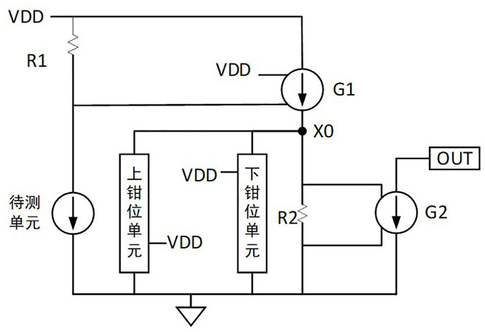
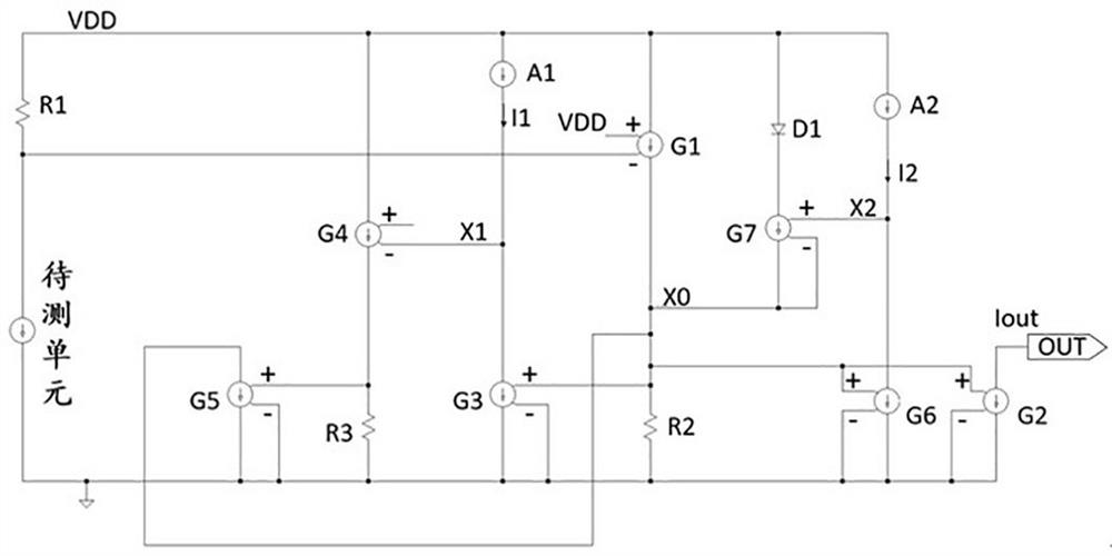
[0044] figure 1 It is a schematic structural diagram of a current detection circuit with controllable detection current according to an exemplary embodiment. like fig...


PUM


Abstract

The present application includes a current detection circuit with controllable detection current, and specifically relates to the technical field of current detection. The circuit includes a unit to be tested, a first resistor, a first controllable current source, a second controllable current source, an upper clamp unit and a lower clamp unit; the power supply voltage end of the circuit passes through the first resistor and the unit to be tested in sequence Grounding; the power supply voltage terminal is grounded sequentially through the first controllable current source and the second resistor; the upper clamping unit is connected to the connection node between the first controllable current source and the second resistor; the lower clamping unit is connected to the first controllable current Connection node of the source to the second resistor. In the above solution, the voltage difference between the two ends of the second resistor is controlled by the upper clamping unit and the lower clamping unit, so that the voltage difference between the two ends of the second resistor is guaranteed to be within a certain range, thereby generating a clamping function for the detection current , no need to add an additional compensation circuit, which reduces the complexity of the current detection circuit and also reduces the cost of the current detection circuit.

Description

technical field [0001] The invention relates to the field of current detection, in particular to a current detection circuit with a controllable detection current. Background technique [0002] In the control loop of the prior art, it is usually necessary to detect the current, and the detected current obtained by the detection is input into the control loop as a control input, so as to realize the normal operation of the control loop. [0003] In order to prevent the detection current obtained by the detection from being too large or too small, so that the control loop will be out of control and the main power circuit will be damaged after the too large or too small detection current is input into the control loop. The detected detection current is clamped and controlled, while in the prior art, when the detection current is clamped and controlled, the current signal is usually converted into a voltage signal, and closed-loop adjustment is performed through an operational a...

Claims


Application Information

Patent Timeline
Patent Type & Authority Patents(China)
IPC IPC(8): G01R19/00
CPCG01R19/0092
Inventor 不公告发明人
Owner SUZHOU BATELAB MICROELECTRONICS
Learn More