Steam generator having steam chamber and metering orifice arranged near rear of steam chamber

A technology of a steam generator and a steam chamber, which is applied to the steam generator field of a garment steamer, can solve problems such as splashing at the outlet of the steam chamber, and achieve the effect of preventing the splashing problem and improving the user experience.

Pending Publication Date: 2022-03-22
KONINKLJIJKE PHILIPS NV
View PDF7 Cites 0 Cited by
  • Summary
  • Abstract
  • Description
  • Claims
  • Application Information

AI Technical Summary

Problems solved by technology

This will cause splashing at the outlet of the vapor chamber

Method used


Image

  • Steam generator having steam chamber and metering orifice arranged near rear of steam chamber
  • Steam generator having steam chamber and metering orifice arranged near rear of steam chamber
  • Steam generator having steam chamber and metering orifice arranged near rear of steam chamber

Examples


Embodiment Construction

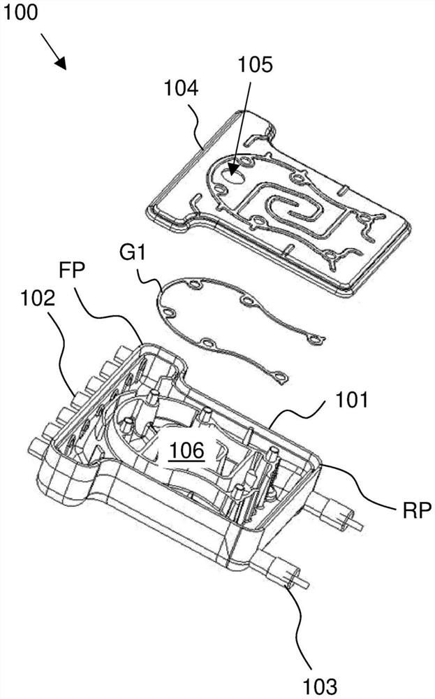
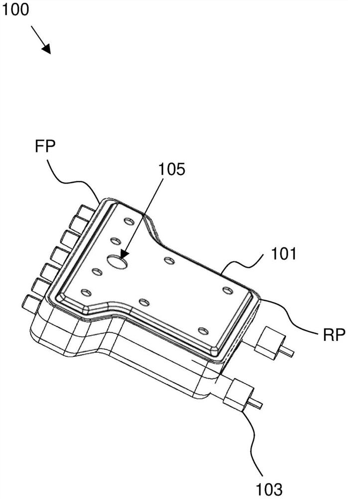
[0040] Figure 2A A first (exploded) view of a steam generator 200 according to the invention is shown, Figure 2B shows as Figure 2A Second (assembled) view of the steam generator shown.

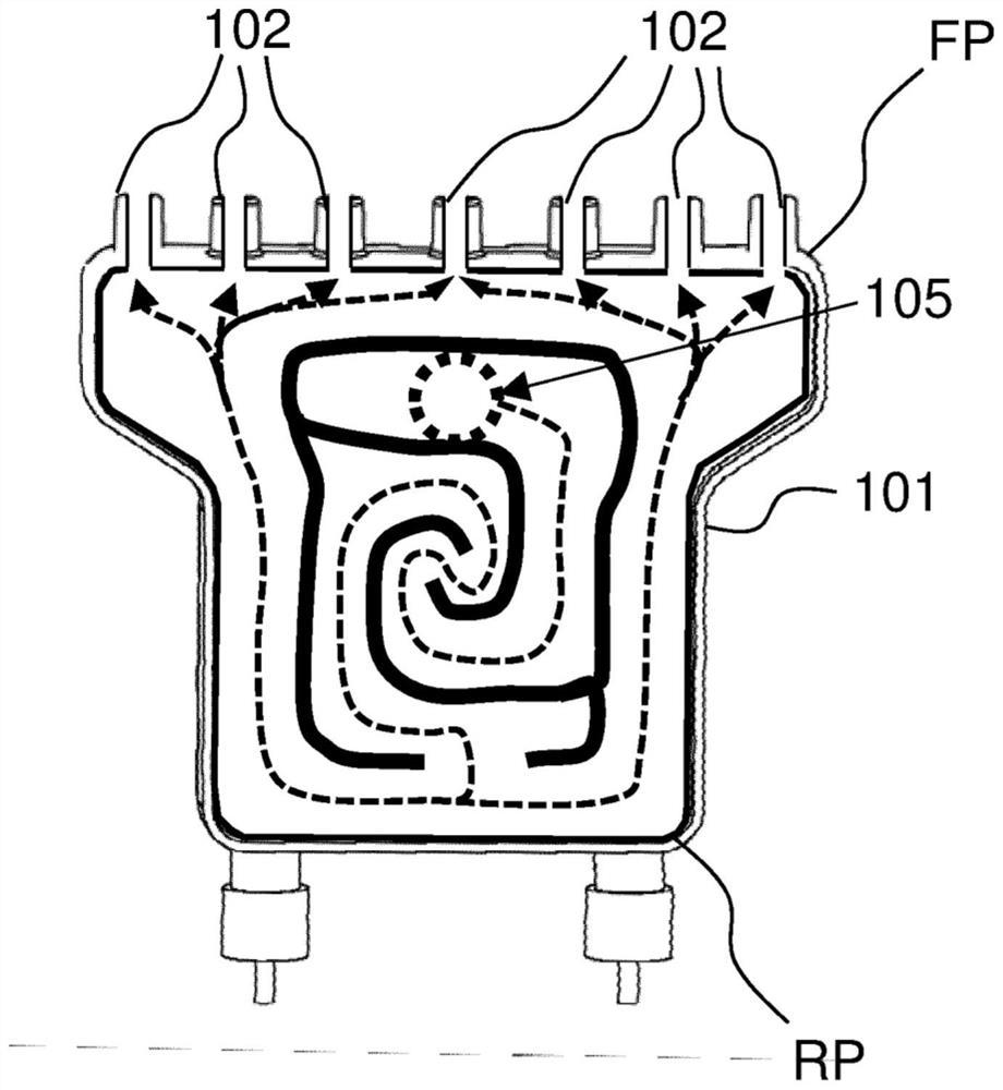
[0041] The steam generator 200 includes a steam chamber 201 for generating steam. The steam chamber 201 extends between the front FP and the rear RP. The steam generator 200 also includes at least one steam outlet 202 arranged at the front FP and receiving steam from the steam chamber 201 .

[0042] The steam generator 200 further includes: a heating element 203 for heating the steam chamber 201 .

[0043] The steam generator 200 also includes a cover 204 adapted to be in a closed position to close the steam chamber 201 . The closed position is Figure 2B shown in .

[0044] The steam generator 200 further includes: a dosing hole 205 arranged in the cover 204 for receiving water and / or steam from the outside of the steam generator 200 . Such as Figure 2B As shown, the dosing aper...


PUM


Abstract

The invention relates to a steam generator (200) comprising a steam chamber (201) for generating steam, said steam chamber (201) extending between a front portion (FP) and a rear portion (RP). The steam generator (200) further comprises at least one steam outlet (202) arranged at the front portion (FP) and receiving steam from the steam chamber (201). The steam generator (200) further comprises a heating element (203) for heating the steam chamber (201) and a cover (204) adapted to be in a closed position to close the steam chamber (201). The steam generator (200) further comprises a metering orifice (205) arranged in said cover (204) for receiving water and / or steam from outside said steam generator (200), said metering orifice (205) being arranged near said rear (RP) when said cover (204) is in said closed position.

Description

technical field [0001] The invention relates to a steam generator, in particular to a steam generator for a garment steamer. [0002] The invention can be used, for example, in the field of garment care. Background technique [0003] Due to the compact size and light weight requirements of steam generators for hand-held steam processors, there is an increased risk of incomplete evaporation of the steam / water dosing in the steam chamber. As a result, water droplets may spread on treated clothing. This problem is known as "splattering". [0004] To overcome this problem, steam / water paths (also known as steam channels) are usually designed as labyrinths and used to extend the water evaporation path to increase contact surface and time to maximize evaporation. The steam channel is also used to direct the flow of steam to reach the steam outlet of the steam chamber. [0005] Traditionally, dosing holes for dosing water and / or steam into such steam generators are located near...

Claims


Application Information

Patent Timeline
Patent Type & Authority Applications(China)
IPC IPC(8): F22B1/28F22B37/36
CPCF22B1/28F22B37/36D06F39/008D06F73/00D06F87/00
Inventor 徐志锋马国华
Owner KONINKLJIJKE PHILIPS NV
Why Eureka
Try Eureka