Metal corrugated foil stamping die

A stamping die and foil technology, which is applied in the field of metal foil forming equipment, can solve the problems of potential safety hazards, impact of stamping equipment, low production efficiency, etc., and achieve the effect of ensuring safe operation

Inactive Publication Date: 2022-03-25
廖慧颖
View PDF0 Cites 0 Cited by
  • Summary
  • Abstract
  • Description
  • Claims
  • Application Information

AI Technical Summary

Problems solved by technology

[0003] However, when the current stamping equipment produces metal corrugated foils, a single stamping can only complete the formation of a single foil during the stroke process, and the stamping equipment cannot perform stamping operations during the return stroke, resulting in low production efficiency of traditional stamping equip

Method used


Image

  • Metal corrugated foil stamping die
  • Metal corrugated foil stamping die
  • Metal corrugated foil stamping die

Examples


Embodiment Construction

[0025] In order to make the technical means realized by the present invention, creative features, goals and effects easy to understand, the present invention will be further elaborated below in conjunction with specific embodiments:

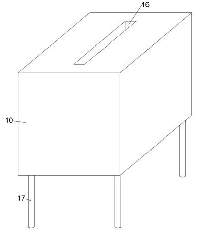
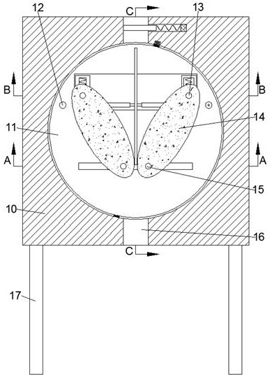
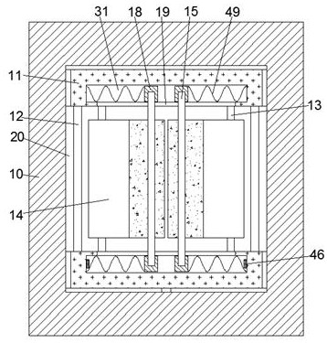
[0026] refer to Figure 1-Figure 6 , a metal corrugated foil stamping die according to an embodiment of the present invention, comprising a main box body 10, two front and back symmetrical turntables 11 are arranged inside the main box body 10, and a Two stamping assemblies for metal foil forming, and a power assembly for providing stamping power is arranged in the turntable 11;

[0027] The two stamping assemblies are symmetrically arranged left and right, and the stamping assembly includes a rolling wheel 14, the rolling wheel 14 is elliptical, and the rolling wheel 14 is equipped with a lower driving lever 15 in rotation, and the lower driving lever 15 is located at the lower focal point of the rolling wheel 14, the front and rear sides of th...


PUM


Abstract

The invention discloses a metal corrugated foil stamping die which comprises a main box body, two rotary discs which are symmetrical front and back are arranged in the main box body, two stamping assemblies used for metal foil forming are arranged between the two rotary discs, and power assemblies used for providing stamping power are arranged in the rotary discs; according to the metal foil rolling forming device, the upper poking rods and the lower poking rods are far away from or close to each other, so that the left and right rolling wheels roll each other, metal foils are rolled and formed, and the upper poking rods on the left and right sides are not interfered when getting close to or far away from each other through the upper poking rod seats capable of sliding up and down; meanwhile, the baffle arranged on the upper side of the rotary disc cavity can be opened only when the rolling wheels on the left side and the right side are in an inverted splayed shape and the symmetry axis of the rolling wheels on the left side and the right side is aligned with the foil through cavity, and therefore it is guaranteed that the metal foil can be rolled and formed by the rolling wheels on the left side and the right side when the metal foil is put into the foil through cavity in the upper side; and the safe operation of the metal corrugated foil forming process is ensured.

Description

technical field [0001] The invention relates to the related technical field of metal foil forming equipment, in particular to a metal corrugated foil stamping die. Background technique [0002] Metal corrugated foil is mainly used in the internal heat dissipation system of the equipment, and its manufacturing process mainly relies on stamping and forming by traditional stamping equipment. [0003] However, when the current stamping equipment produces metal corrugated foils, a single stamping can only complete the formation of a single foil during the stroke process, and the stamping equipment cannot perform stamping operations during the return stroke, resulting in low production efficiency of traditional stamping equipment , and the traditional stamping equipment needs to manually place the metal foil on the mold when stamping, and remove the formed metal corrugated foil after the stamping is completed. During this process, if the worker does not operate properly, it is eas...

Claims


Application Information

Patent Timeline
IPC IPC(8): B21D37/10B21D33/00
CPCB21D37/10B21D33/00
Inventor 廖慧颖
Owner 廖慧颖
Why Eureka
Try Eureka