Support conveyor

A technology for conveyors and shells, applied in the field of stent conveyors and conveyors, which can solve problems such as large pushing force, structural limitations of the conveying system, and inconvenient surgical operations for medical staff, so as to ensure safe operation and avoid tremors and offsets. Effect

Active Publication Date: 2016-12-14
SUZHOU TIANHONGSHENGJIE MEDICAL INSTR CO LTD
View PDF12 Cites 2 Cited by
  • Summary
  • Abstract
  • Description
  • Claims
  • Application Information

AI Technical Summary

Problems solved by technology

[0003] Due to the limitation of the length of the vascular stent, the structure of the delivery system of the existing stent delivery device is not convenient for the medical staff to perform the operation, requiring two-handed operation, and tremors and deviations are likely to occur during the delivery process of the long delivery stroke, and the delivery is not easy. Stable, severe cases may even cause the vascular stent to deviate, affecting the normal progress of the operation
The conveying system will suspend the conveying operation during the conveying process. At this time, the operator needs to hold the conveying system, which is extremely inconvenient. However, the conveying system in the prior art has two-level pause buttons, but during the operation, the pause operation may occur at any time. Level pause button doesn't meet needs
There is a certain resistance during the delivery of the vascular stent, and there is also a certain amount of friction in the pushing mechanism of the delivery system, which leads to a large push force required for the delivery system, which is not convenient for medical staff to operate, and the push strength is relatively high, and due to the push force If it is too large, it will easily lead to unstable delivery of the stent, tremor and deviation, etc. In severe cases, it may even cause deviation of the stent, which will affect the normal progress of the operation

Method used


Image

  • Support conveyor
  • Support conveyor
  • Support conveyor

Examples


Embodiment 1

[0019] The following definitions of directions are all defined according to the directions observed by the user when holding the stent transporter.

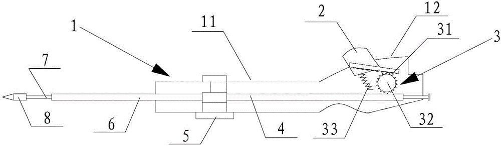
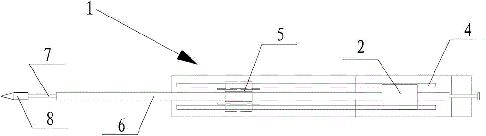
[0020] Such as figure 1 and figure 2 The shown stent delivery device mainly includes a housing 1, a trigger 2, a transmission mechanism 3, an outer sheath 6, a central catheter 7, and the like.

[0021] Wherein, the casing 1 includes a straight pipe portion 11 and a handle portion 12, which can be set as one or detachable according to needs; in addition, the casing 1 can be set to be composed of two symmetrical parts, and the actual user can put the They are disassembled to replace damaged parts. The trigger 2 is installed on the housing 1, and only needs to be pressed when using the support conveyor. Part of the central conduit 7 is located in the housing 1 , its rear end is fixed or mounted on the housing 1 (it can also extend out of the housing 1 ), and its front end extends out of the housing 1 . The outer sheath 6 is sl...

Embodiment 3

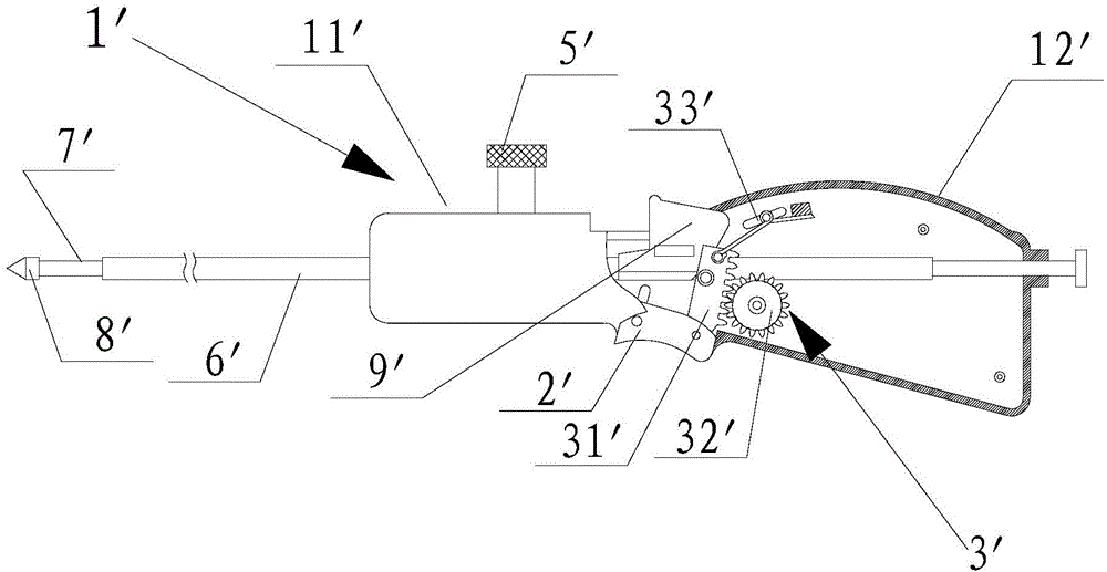
[0024] Such as image 3 The structure of the shown stent delivery device is similar to that of the delivery device in Embodiment 1, and also includes components such as a housing 1', a trigger 2', a transmission mechanism 3', an outer sheath tube 6', and a central catheter 7'.

[0025] The housing 1' includes a straight pipe part 11' and a handle part 12', which can be set as one or detachable as required; in addition, the housing 1' can be set to be composed of two symmetrical parts. They can be disassembled to replace damaged parts. The trigger 2' is installed on the housing 1', and only needs to be pressed when using the support conveyor. The part of the central conduit 7' is located in the casing 1', its rear end is fixed or installed on the casing 1' (it can also extend outside the casing 1'), and its front end extends outside the casing 1' ( This end is fitted with a tip 8' located outside the outer sheath 6'). The outer sheath tube 6' is slidably sleeved on the centr...


PUM


Abstract

The invention relates to a support conveyor. The support conveyor comprises a shell body, a trigger installed on the shell body, a center duct which is installed in the shell body and has an end extending to exterior of the shell body, as well as an outer sheath tube which can sleeve the center duct in a sliding manner. The conveyor also comprises a transmission mechanism which is installed in the shell body and connected to the trigger and the outer sheath tube respectively, wherein the transmission mechanism comprises a transmission gear connected to the surface of the center duct, a rack meshed with the transmission gear and connected with the trigger, as well as an elastic part which has an end connected to the trigger and is used to reset the trigger. In this way, vibration and skewing of the conveyor generated in a long conveying stroke can be avoided; starting and stopping of conveying can be controlled easily; conveying formation of the center duct can be controlled accurately; and safe implementation of operations can be ensured.

Description

technical field [0001] The invention belongs to the field of medical enterprises, and relates to a conveyor, in particular to a bracket conveyor. Background technique [0002] Peripheral vascular surgery is a traditional method for the treatment of peripheral vascular stenosis. Compared with traditional peripheral vascular surgery, stent therapy is a minimally invasive interventional operation using stents with less trauma, fewer complications, and better results. It has become the current treatment for peripheral vascular stenosis. main method. Implanting a vascular stent into the body requires the use of a delivery system. In the prior art, a hollow inner tube and an outer tube are generally used. The hollow part of the inner tube is convenient for the guide wire to pass through the tube during the operation. Between the outer tubes; during surgery, the guide wire guides the catheter assembly of the delivery system to the surgical site, and the control assembly makes the ...

Claims


Application Information

Patent Timeline
IPC IPC(8): A61F2/966
CPCA61F2/9517A61F2/966A61F2002/9665
Inventor 李晓强冯海全王晓天唐烈王永刚
Owner SUZHOU TIANHONGSHENGJIE MEDICAL INSTR CO LTD
Why Eureka
Try Eureka