Automatic sleeve machining device and machining method thereof

A technology of automatic processing and casing, applied in the direction of manufacturing tools, decorative arts, other manufacturing equipment/tools, etc., can solve problems such as low efficiency and inconsistent product quality, and achieve the effect of uniform processing quality and reduced labor costs.

Active Publication Date: 2022-03-25
NINGBO SANLING ELECTRONICS
View PDF7 Cites 0 Cited by
  • Summary
  • Abstract
  • Description
  • Claims
  • Application Information

AI Technical Summary

Problems solved by technology

[0002] In engineering construction, the construction of electrical lines is becoming more and more strict. In order to ensure the safety and reliability of electrical lines, wires are usually inserted into the wire tubes. Because the length of a single wire tube is limited, a sleeve is usually required to connect two wire tubes; figure 1 As shown, the existing casing includes a tube body 01a, the middle part of the tube body 01a is rolled with inner ribs 01b, and the inner ribs 01b are set to facilitate the positioning of the inserted wire tube; the outer side of the tube body 01a has two inner ribs 01b There is a threaded hole 01c on the side, and the threaded hole 01c is set so that the bolt can be screwed in to lock the wire tube in the casing; in addition, in order to facilitate the casing user to identify the type of casing, it is usually stamped on the outer circumference of the casing The type and other information of the sleeve, and in order to facilitate the insertion of the wire tube from both ends of the sleeve, the inner chamfer 01d will be set at the open end of the sleeve. The existing sleeve production is processed by manual steps, not only the efficiency Low, and the quality of processed products is not uniform

Method used


Image

  • Automatic sleeve machining device and machining method thereof
  • Automatic sleeve machining device and machining method thereof
  • Automatic sleeve machining device and machining method thereof

Examples


Embodiment Construction

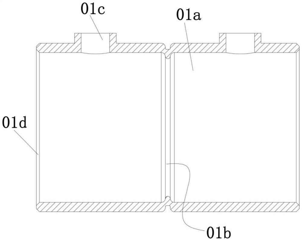
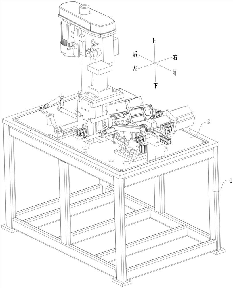
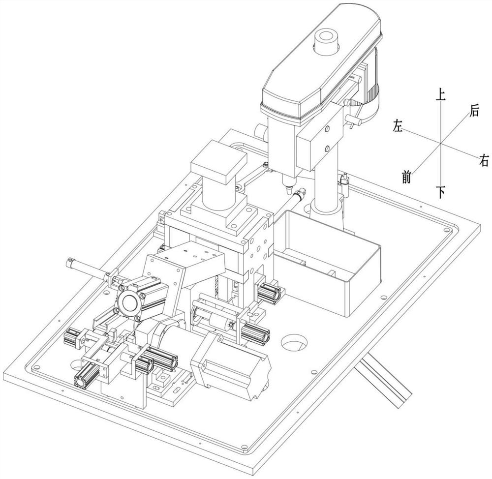
[0050] Such as Figure 1-43 As shown, a casing automatic processing device provided in this embodiment includes a table frame, and a table plate is provided on the table frame, and a detection mechanism, a casing clamping mechanism, and a character embossing mechanism are arranged on the table plate. , a bead rolling mechanism, a punching transmission mechanism, and a tapping mechanism, the detection mechanism is used to detect whether there is an inner chamfer at both ends of the sleeve, and send the sleeve with the inner chamfer at both ends into the sleeve clamping mechanism middle; the sleeve clamping mechanism is used to laterally fix the sleeve; the character embossing mechanism is used to emboss characters on the outside of the circumference of the sleeve fixed in the sleeve clamping mechanism; the rolling mechanism is used It is used to roll the inner ribs of the casing fixed in the casing clamping mechanism; the punching transmission mechanism is used to receive the c...


PUM


Abstract

The invention discloses an automatic casing pipe machining device and a machining method.The automatic casing pipe machining device comprises a table frame, a table plate is arranged on the table frame, and a detection mechanism, a casing pipe clamping mechanism, a character impressing mechanism, a rib rolling mechanism, a punching conveying mechanism and a tapping mechanism are arranged on the table plate; the detection mechanism is used for detecting whether inner chamfers exist at the two ends of the casing pipe or not and feeding the casing pipe with the inner chamfers at the two ends into the casing pipe clamping mechanism; the sleeve clamping mechanism is used for transversely fixing a sleeve; the character impressing mechanism is used for impressing characters on the outer side of the circumference of the sleeve; the rib rolling mechanism is used for rolling the inner convex ribs of the sleeve; the punching conveying mechanism is used for receiving the casing pipe in the casing pipe clamping mechanism, completing punching and then sending the punched casing pipe into the tapping mechanism, the tapping mechanism is used for tapping, the automatic casing pipe machining device can achieve casing pipe machining, then manual operation is replaced, the labor cost is reduced, and meanwhile it is guaranteed that the machining quality of the casing pipe is unified.

Description

technical field [0001] The invention relates to the field of electrical pipe casing manufacturing, in particular to an automatic casing processing device and a processing method thereof. Background technique [0002] In engineering construction, the construction of electrical lines is becoming more and more strict. In order to ensure the safety and reliability of electrical lines, wires are usually inserted into the wire tubes. Because the length of a single wire tube is limited, a sleeve is usually required to connect two wire tubes; figure 1 As shown, the existing casing includes a tube body 01a, the middle part of the tube body 01a is rolled with inner ribs 01b, and the inner ribs 01b are set to facilitate the positioning of the inserted wire tube; the outer side of the tube body 01a has two inner ribs 01b There is a threaded hole 01c on the side, and the threaded hole 01c is set so that the bolt can be screwed in to lock the wire tube in the casing; in addition, in order...

Claims


Application Information

Patent Timeline
IPC IPC(8): B23P23/04B44B5/00B44B5/02
CPCB23P23/04B44B5/00B44B5/02
Inventor 吴昌林沈智毅胡修涛
Owner NINGBO SANLING ELECTRONICS
Why Eureka
Try Eureka