Multi-position anchor cable construction device

A construction device and multi-position technology, applied in the installation of bolts, drilling equipment, drilling equipment and methods, etc., can solve problems such as the falling off of the anchor cable tray, insufficient angle of the shoulder socket and the anchor cable, and inconvenient adjustment of the anchor cable angle. , to achieve the effect of increasing the anchoring depth

Pending Publication Date: 2022-03-25
HUAIBEI MINING IND
View PDF0 Cites 0 Cited by
  • Summary
  • Abstract
  • Description
  • Claims
  • Application Information

AI Technical Summary

Problems solved by technology

In the process of strengthening support, the anchor cables are often constructed at the side and shoulder sockets, but when using a bolter for construction, the angle of the shoulder sockets and the side anchor cables is not enough. When the anchor cables are pressurized to the design pre-tightening force, the anchor cables The tray is bent, the anchor cable is cut, the greater the deformation of the roadway, the greater the shear force, and eventually the anchor cable is cut, the anchor cable tray falls off, and the safety hazard is great. However, the existing problems are summarized as follows: 1. It is not easy to Adjust the angle of the anchor cable; 2. It is not convenient to adjust the eye position of the anchor cable through the hole height of the anchor cable, making it impossible to meet the diversified market demand

Method used


Image

  • Multi-position anchor cable construction device
  • Multi-position anchor cable construction device
  • Multi-position anchor cable construction device

Examples


Embodiment Construction

[0021] Referring to the accompanying drawings, through the description of the embodiments, the specific embodiments of the present invention such as the shape of each member involved; structure; the mutual position and connection relationship between each part; the role and working principle of each part; manufacturing process And the method of operation and use, etc., for further detailed explanation, to help those skilled in the art to the inventive concept of the present invention; Technical solution has more complete; Accurate and in-depth understanding.

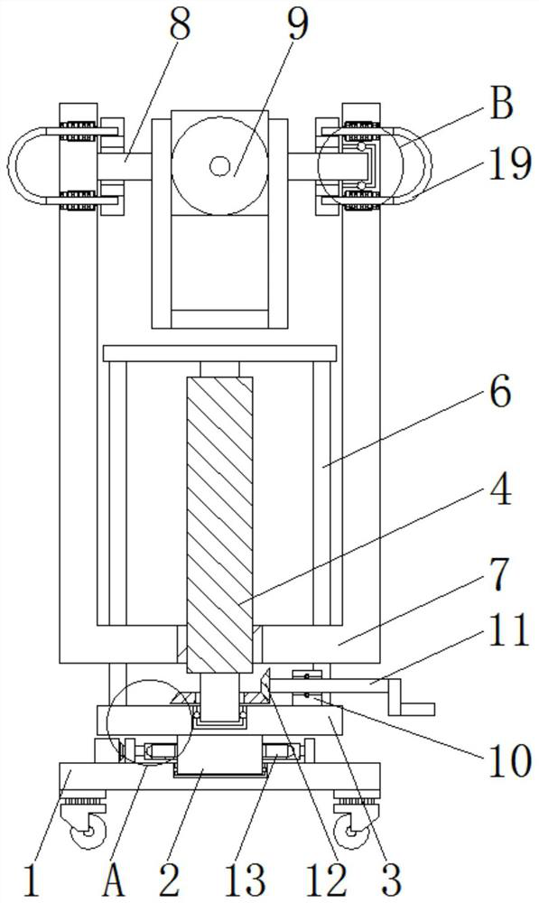
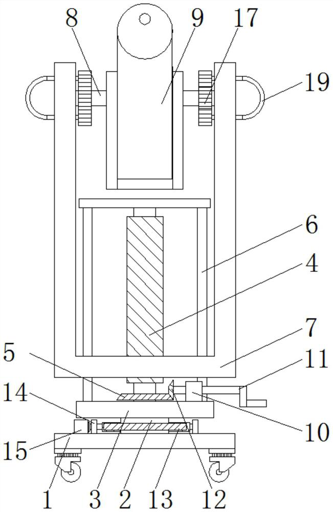
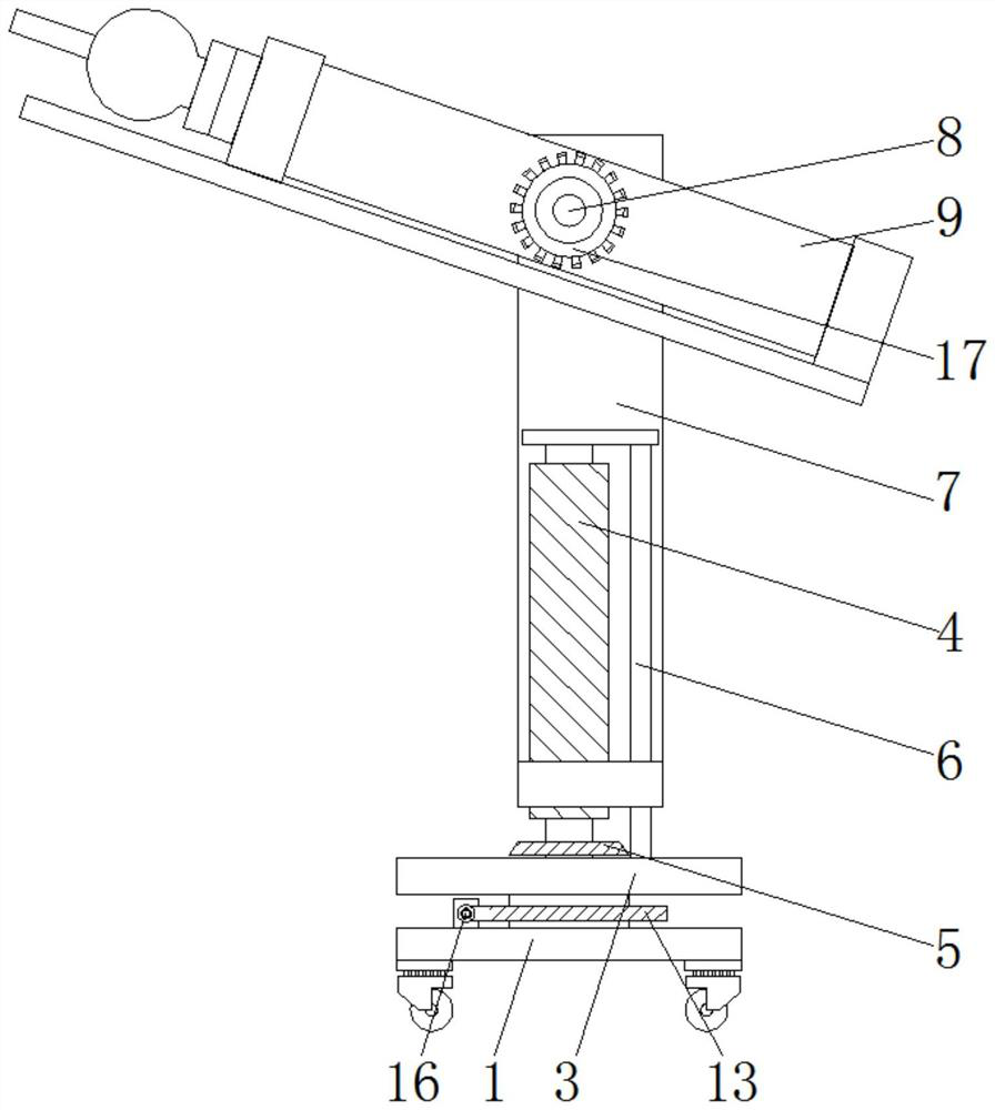
[0022] Figure 1-5 The multi-position anchor cable construction device shown includes a support base plate 1, a fixed shaft 2, a lifting frame 7 and an anchor cable frame 9, the top of the support base plate 1 is installed with a fixed shaft 2 through a bearing, and a turntable is arranged on the top of the fixed shaft 2 3. The outer wall of the fixed shaft 2 is provided with a transmission mechanism for free rotation. T...


PUM


Abstract

The multi-position anchor cable construction device comprises a supporting bottom plate, a fixing shaft, a lifting frame and an anchor cable rack, the fixing shaft is installed at the top end of the supporting bottom plate through a bearing, a rotating disc is arranged at the top end of the fixing shaft, a transmission mechanism used for free rotation is arranged on the outer wall of the fixing shaft, and a lead screw is installed at the top end of the rotating disc through a bearing; guide rods are arranged at the two ends of the top end of the rotary disc, a lifting frame penetrating through the guide rods is arranged on the outer wall of the lead screw, the interior of the lifting frame is meshed with the outer wall of the lead screw, movable shafts are installed on the inner side of the lifting frame through bearings, and an anchor cable rack is arranged between the movable shafts. A limiting mechanism used for fixing the position of the anchor cable rack is arranged in the lifting frame. By the adoption of the technical scheme, the problems of construction shoulder nests of the anchor cable machine and the angle of the anchor cable on the side are solved, and the effective vertical anchoring depth of the anchor cable is increased.

Description

technical field [0001] The invention belongs to the field of mine protection devices, and more specifically, the invention relates to a multi-position anchor cable construction device. Background technique [0002] With the extension of mine mining, the roadway is buried deeper and deeper, the ground pressure increases accordingly, the mine pressure is obvious, and the roadway support level is enhanced. In the process of strengthening support, the anchor cables are often constructed at the side and shoulder sockets, but when using a bolter for construction, the angle of the shoulder sockets and the side anchor cables is not enough. When the anchor cables are pressurized to the design pre-tightening force, the anchor cables The tray is bent, the anchor cable is cut, the greater the deformation of the roadway, the greater the shear force, and eventually the anchor cable is cut, the anchor cable tray falls off, and the safety hazard is great. However, the existing problems are ...

Claims


Application Information

Patent Timeline
Patent Type & Authority Applications(China)
IPC IPC(8): E21D20/00E21B7/02E21B7/04
CPCE21D20/003E21D20/00E21B7/02E21B7/04
Inventor 武志俊
Owner HUAIBEI MINING IND
Why Eureka
Try Eureka