Rotor structure, motor, compressor and air conditioner

A rotor structure and compressor technology, applied in the field of compressors, can solve the problems of insufficient suction capacity and suction pressure loss, and achieve the effects of reducing loss, weight, and cooling capacity loss.

Active Publication Date: 2022-03-25
GREE ELECTRIC APPLIANCES INC
View PDF5 Cites 0 Cited by
  • Summary
  • Abstract
  • Description
  • Claims
  • Application Information

AI Technical Summary

Problems solved by technology

[0003] Therefore, the present invention solves the technical problem that the rotor suction pressure loss in the low-pressure chamber of the existing scroll compressor leads to insufficient suction volume

Method used


Image

  • Rotor structure, motor, compressor and air conditioner
  • Rotor structure, motor, compressor and air conditioner
  • Rotor structure, motor, compressor and air conditioner

Examples


Embodiment Construction

[0036] In order to make the purpose, technical solution and advantages of the present invention clearer, the technical solution of the present invention will be clearly and completely described below in conjunction with specific embodiments of the present invention and corresponding drawings. Apparently, the described embodiments are only some of the embodiments of the present invention, but not all of them. Based on the embodiments of the present invention, all other embodiments obtained by persons of ordinary skill in the art without making creative efforts belong to the protection scope of the present invention.

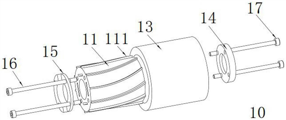
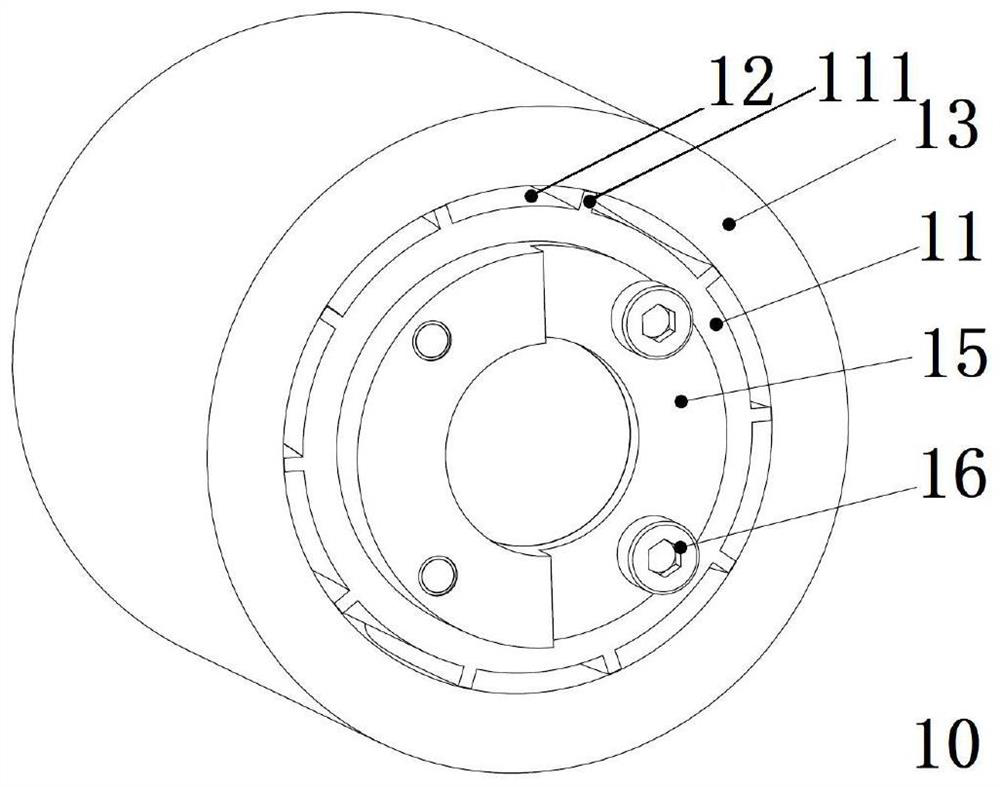
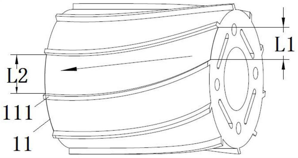
[0037] combine Figure 1-10 As shown, the present invention provides a rotor structure, including: a rotor assembly 10, the rotor assembly 10 is provided with a pressurized passage 12, when the rotor assembly 10 rotates, the pressurized passage 12 can make the first end of the rotor assembly 10 and The second end generates a pressure difference to pressurize the ...


PUM


Abstract

The invention provides a rotor structure, a motor, a compressor and an air conditioner, and the rotor structure comprises a rotor assembly, the rotor assembly is provided with a pressurization channel, when the rotor assembly rotates, the pressurization channel can enable a first end and a second end of the rotor assembly to generate a pressure difference, and gas flowing through the pressurization channel is pressurized; therefore, the sucked air can be pressurized, the loss of air suction pressure is reduced, the loss of refrigerating capacity of the compressor is reduced, the requirement for the air suction capacity of the compressor at different rotating speeds is met, meanwhile, an air suction channel does not need to be independently arranged on the shell of the motor, and the weight of the compressor is reduced.

Description

technical field [0001] The invention belongs to the technical field of compressors, and in particular relates to a rotor structure, a motor, a compressor and an air conditioner. Background technique [0002] The current vortex rotor is divided into a high-pressure chamber rotor and a low-pressure chamber rotor. The suction of the rotor in the low-pressure chamber will pass through the motor, and there will be a certain loss of suction pressure, which will lead to changes in the working state of the compressor, resulting in refrigeration of the compressor. amount becomes smaller. And when the rotor rotates at a high speed, it needs to inhale more gas. The air intake channels of the existing rotors are all fixed. To ensure the air intake of the rotor, the housing needs to be designed to be larger to ensure the air intake. fulfil requirements. Contents of the invention [0003] Therefore, the present invention solves the technical problem that the rotor suction pressure los...

Claims


Application Information

Patent Timeline
Patent Type & Authority Applications(China)
IPC IPC(8): F04C29/12F04D29/32F04D29/38H02K1/22F04C23/02
CPCF04C29/122F04D29/321F04D29/324H02K1/22F04C23/02
Inventor 李奎林吴小鸿李凤林鸿新叶益青肖汉龙
Owner GREE ELECTRIC APPLIANCES INC
Why Eureka
Try Eureka