an injection mold

A technology of injection molds and molds, which is applied in the field of injection molds, can solve the problems of inconvenient removal of injection molded products, and achieve the effects of novel design, convenient use, and convenient removal

Active Publication Date: 2021-06-25
佛山市力晟塑胶制品有限公司
View PDF15 Cites 0 Cited by
  • Summary
  • Abstract
  • Description
  • Claims
  • Application Information

AI Technical Summary

Problems solved by technology

[0004] The existing injection molds are divided into upper and lower molds. After the injection molding is completed, it is not convenient to remove the injection molded products because part of the injection molded products is in the mold flow channel.

Method used


Image

  • an injection mold
  • an injection mold
  • an injection mold

Examples


Embodiment 1

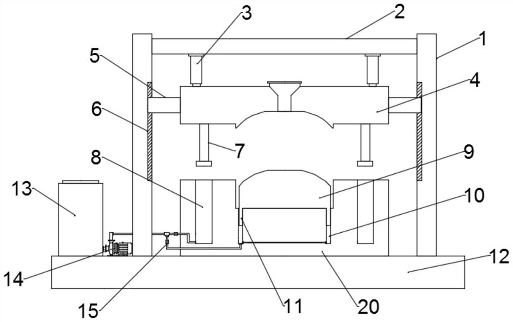
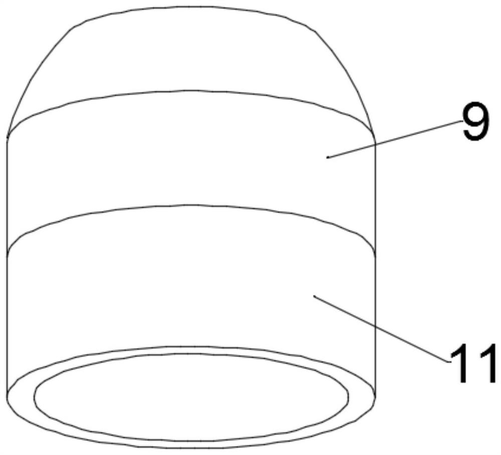
[0022] see figure 1 and 3 , in an embodiment of the present invention, an injection mold, an upper mold 4, a bottom plate 12 and a lower mold 20; the lower mold 20 is installed on the bottom plate 12, and the upper end of the bottom plate 12 is fixed with a crossbeam 2 through two symmetrically arranged brackets 1 , the upper mold 4 is driven by the driving assembly installed on the beam 2 to move up and down, the lower mold 20 is provided with a movable mold 9, and the movable mold 9 forms an injection flow channel with the upper mold 4 and the lower mold 20, so The lower end of the movable mold 9 is fixed with an annular block 11, and the annular block 11 is placed in the annular oil chamber 10 provided on the lower mold 20, and the annular oil chamber 10 communicates with the oil supply assembly. During the specific use process, the annular block 11 Placed in the annular oil chamber 10, the oil supply assembly absorbs the hydraulic oil in the annular oil chamber 10, so tha...

Embodiment 2

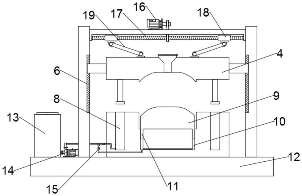
[0029] see figure 2 and 3 During the specific implementation process of the present invention, another embodiment is proposed to improve the present application. Specifically, the drive assembly includes a motor 16, a bidirectional threaded rod 17 and a threaded sleeve 18, and the bidirectional threaded rod 17 is arranged horizontally. And its two ends are respectively rotated and installed on the support 1, and the output shaft of the described motor 16 is connected with the described two-way threaded rod 17 by transmission belt, and two-way threaded rod 17 is symmetrically provided with two threaded sleeves 18, and the threaded sleeve 18 The lower end of the lower end is hinged with the upper end of the upper mold 4 through the connecting rod 19 hinged therewith. When the motor 16 drives the two-way threaded rod 17 to rotate, the upper mold 4 is driven to move vertically under the action of the threaded sleeve 18 and the connecting rod 19.

[0030] It should be noted that ...


PUM


Abstract

The invention relates to the technical field of injection molds, in particular to an injection mold, an upper mold, a bottom plate and a lower mold; the lower mold is installed on the bottom plate, and the upper end of the bottom plate is fixed with a beam through two symmetrically arranged brackets, and the upper mold Driven by the driving assembly installed on the crossbeam to move up and down, the lower mold is provided with a movable mold, and the movable mold forms an injection flow channel with the upper mold and the lower mold. The lower end of the movable mold is fixed with a ring block, and the ring block It is placed in the annular oil cavity provided on the lower mold, and the annular oil cavity communicates with the oil supply assembly. The invention is novel in design, and the oil supply assembly absorbs the hydraulic oil in the annular oil cavity, so that negative pressure is generated in the annular oil cavity, and the movable mold is fixed. When the mold needs to be removed, the oil supply assembly supplies The oil plays the role of pressurization, so that the product after injection molding and cooling is moved up together with the movable mold, which is convenient for taking out the molded product.

Description

technical field [0001] The invention relates to the technical field of injection molds, in particular to an injection mold. Background technique [0002] Injection mold is a tool for producing plastic products; it is also a tool for giving plastic products complete structure and precise dimensions. Injection molding is a processing method used in the mass production of certain complex-shaped parts. Specifically, it refers to injecting the heated and melted plastic into the mold cavity under high pressure from the injection molding machine, and after cooling and solidifying, a molded product is obtained. [0003] Injection molds are divided into thermosetting plastic molds and thermoplastic plastic molds according to the molding characteristics; according to the molding process, they are divided into transfer molds, blow molds, casting molds, thermoforming molds, hot compression molds (compression molds), injection molds, etc. Among them, the hot pressing mold can be divide...

Claims


Application Information

Patent Timeline
Patent Type & Authority Patents(China)
IPC IPC(8): B29C45/33B29C45/17
CPCB29C45/1742B29C45/33
Inventor 易伟青
Owner 佛山市力晟塑胶制品有限公司
Why Eureka
Try Eureka