
Tower grounding device and operation method

A grounding device and tower technology, which is applied to the parts of the connecting device, the connecting ground, the coupling device, etc., can solve the problems such as the inability to meet the requirements of large current discharge, the small contact area of ​​the ground, and the fixed grounding wire. Improve current dissipation capacity, good grounding effect, and firm installation

Active Publication Date: 2022-03-25
ELECTRIC POWER OF HENAN LUOYANG POWER SUPPLY
View PDF12 Cites 0 Cited by
  • Summary
  • Abstract
  • Description
  • Claims
  • Application Information

AI Technical Summary

Problems solved by technology

[0002] The grounding device refers to the general term for the grounding electrode buried in the ground and the connecting wire from the grounding electrode to the equipment. The grounding device is composed of a grounding body (round steel, angle steel, flat steel, steel pipe, etc.) With the continuous increase of power transmission capacity of the power grid, when the transmission line fails, the magnitude of the short-circuit current will also continue to increase. Insulator grounding short-circuit fault occurs in the room, etc. In order to ensure the safety of power grid operation, it is necessary to flow the large current on the upper side of the power line into the ground through the grounding wire to avoid tripping of the power line. The existing grounding device is extremely inconvenient to install. It does not need to be fixed, and the contact area with the ground is small, which cannot meet the requirements of large current discharge to the ground

Method used


Image

  • Tower grounding device and operation method
  • Tower grounding device and operation method
  • Tower grounding device and operation method

Examples


Embodiment

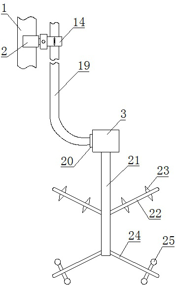
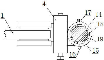
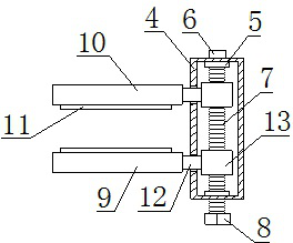
[0017] Such as Figure 1-3 As shown, a grounding device and operation method for a pole tower, which includes a tower foot 1, a clamping mechanism 2 and a grounding mechanism 3, the outside of the tower foot 1 is provided with a clamping mechanism 2, and the middle of the clamping mechanism 2 is provided There is a socket 4, a block 5 is arranged on the inner side of the socket 4, a rotating shaft 6 is arranged in the middle of the block 5, an external thread 7 is arranged on the surface of the rotating shaft 6, and the front side of the rotating shaft 6 is arranged There is a chuck 8, and the left side of the socket 4 is provided with a front splint 9 and a rear splint 10, and the inner sides of the front splint 9 and the rear splint 10 are provided with anti-skid pads 11, and the front splint 9 and the rear splint 10 are provided with 10 right side is provided with slide block 13, and described front splint 9 and rear splint 10 are fixed with slide block 13 by connecting rod...


PUM


Abstract

The invention relates to a pole tower grounding device and an operation method, the pole tower grounding device comprises a tower foot, a clamping mechanism and a grounding mechanism, when the pole tower grounding device is used, the clamping mechanism and the tower foot are fixed firstly, a clamping head is rotated through a wrench, the clamping head drives a rotating shaft to rotate, then a sliding block is driven to move, and under the action of the sliding block, the grounding mechanism is fixed; the front clamping plate and the rear clamping plate can be close to or far away from each other at the same time, so that a tower foot is clamped, a grounding wire is placed in the semi-ring, the semi-ring is buckled and pressed, the grounding wire is fixed in the lantern ring, the lower end of the grounding wire is connected with the grounding mechanism, the grounding mechanism is composed of a middle rod and a bottom rod, and current can be rapidly guided into soil through shunting needles on the outer side of the middle rod. The current diffusing capability of the grounding mechanism can be improved, the contact area between the grounding mechanism and the ground can be increased through the diffusing balls on the outer side of the bottom rod, large current can be evacuated in time, and use safety is guaranteed. The grounding device has the advantages of being firm in installation, high in stability and good in grounding effect.

Description

technical field [0001] The invention belongs to the technical field of pole tower grounding devices, and in particular relates to a pole tower grounding device and an operation method. Background technique [0002] The grounding device refers to the general term for the grounding electrode buried in the ground and the connecting wire from the grounding electrode to the equipment. The grounding device is composed of a grounding body (round steel, angle steel, flat steel, steel pipe, etc.) With the continuous increase of power transmission capacity of the power grid, when the transmission line fails, the magnitude of the short-circuit current will also continue to increase. Insulator grounding short-circuit fault occurs in the room, etc. In order to ensure the safety of power grid operation, it is necessary to flow the large current on the upper side of the power line into the ground through the grounding wire to avoid tripping of the power line. The existing grounding device ...

Claims


Application Information

Patent Timeline
Patent Type & Authority Applications(China)
IPC IPC(8): H01R4/66H01R4/38H01R13/02H01R13/502H02G13/00
CPCH01R4/66H01R4/38H01R13/02H02G13/40H01R13/502Y02E10/72
Inventor 李婷和小波王晨晨申莹莹杜娜丹倩韩啸旭史晓燕王占波石恒星
Owner ELECTRIC POWER OF HENAN LUOYANG POWER SUPPLY
Learn More