Novel power line adapter connector

A technology for transfer connectors and power cords, applied in the direction of connection, two-part connection devices, circuits, etc., can solve the problems of increasing operations, increasing the number of sleeve disassembly, and affecting the service life of products, so as to reduce operations and improve wiring Efficiency, the effect of increasing the service life

Pending Publication Date: 2022-03-25
CHINA AVIATION OPTICAL-ELECTRICAL TECH CO LTD
View PDF11 Cites 0 Cited by
  • Summary
  • Abstract
  • Description
  • Claims
  • Application Information

AI Technical Summary

Problems solved by technology

The disadvantage of this structure is that when it is necessary to perform wiring or disconnection operations, the wiring insulator needs to be taken out of the sleeve as a whole, so that the wiring ports on both sides of the wiring insulator are exposed, even if only the wires on one side of the wiring insulator need to be connected. For disassembly, only to expose the wiring ports on one side, the sleeve must be completely removed to expose two wiring ports at the same time, which increases redundant operations and increases the number of disassembly of the sleeve, which affects the service life of the product

Method used


Image

  • Novel power line adapter connector
  • Novel power line adapter connector
  • Novel power line adapter connector

Examples


Embodiment 1

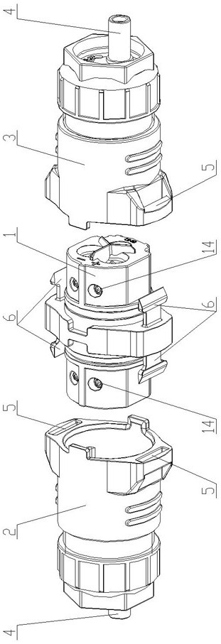
[0031] Embodiment one: see figure 1 , the base sleeve 2 and the movable sleeve 3 of this embodiment have adopted exactly the same structure, the outer sides of the movable sleeve 3 and the base sleeve 2 are provided with claw grooves 5, and the wiring insulator 1 is provided with two sockets for respectively inserting them. There are multiple claws 6 in the side claw groove 5, and the inner side of the wiring insulator 1 is provided with a contact piece 13. The two ends of the wire 4 extend from the outside of the two sleeves respectively, and then extend into the contact piece 13 and pass through the wiring insulator. 1, screw the crimping screw 14 that establishes and compress, realize the energization connection of both sides lead wire 4.

[0032] The two sleeves and the wiring insulator 1 are connected in the form of the claw 6 and the claw groove 5. After the wire 4 is connected, the sleeve and the wiring insulator 1 can be directly inserted in pairs to realize the instal...

Embodiment 2

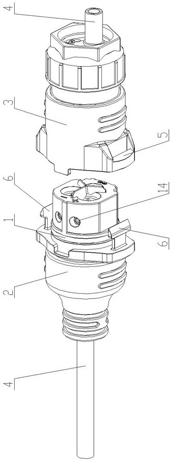
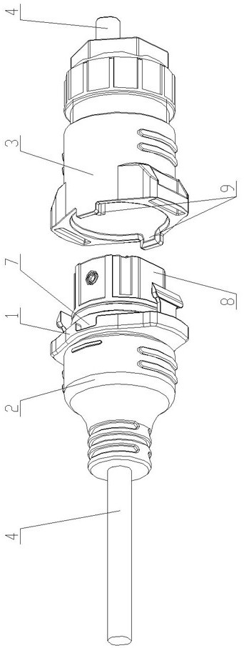
[0033] Embodiment two: see Figure 2-8 , the outer side of the movable sleeve 3 of this embodiment is provided with claw grooves 5, and the wiring insulator 1 is provided with claws 6, and the basic sleeve 2 is plastic-sealed and fixed to the wires 4 extending into its interior, and the basic sleeve 2 is fixed on the wiring On the insulator 1, so that the basic sleeve 2 can be plastic-sealed in advance during the production process, and it is integrated with the wiring insulator 1 during production. When it is used on site, it is only necessary to wire one side of the movable sleeve 3. The basic sleeve 2 is no longer disassembled, which simplifies the on-site wiring process, further reduces the redundant operation of disassembling the sleeve, and reduces the wear and tear on the product caused by multiple disassembly.

[0034] The outer side of the wiring insulator 1 is provided with an anti-rotation groove 7 and an anti-rotation flat 8, and the inner side of the movable sleev...


PUM


Abstract

A novel power line adapter connector comprises a wiring insulator, a basic sleeve and a movable sleeve, wiring ports are formed in the wiring insulator, contact pieces are arranged in the wiring ports, and the basic sleeve and the movable sleeve are arranged on the outer sides of the wiring ports on the two sides of the wiring insulator in a sleeving mode respectively. The two ends of the wire extend into the basic sleeve and the movable sleeve respectively and are connected with the contact piece, the basic sleeve is independently connected with the wiring insulator, the movable sleeve is detachably connected with the wiring insulator or the basic sleeve, and when the wire of the wiring port on one side of the movable sleeve is disassembled, only the movable sleeve needs to be disassembled, so that the wire can be disassembled conveniently. According to the utility model, the base sleeve and the movable sleeve do not need to be disassembled completely, and the situation that the sleeve needs to be disassembled completely and two wiring ports need to be exposed at the same time even if only one wiring port is exposed in the prior art is avoided, so that redundant operation is reduced, the disassembly frequency of the sleeve is reduced, and the service life of a product is prolonged.

Description

technical field [0001] The invention relates to the field of power cord transfer connectors, in particular to a novel power cord transfer connector. Background technique [0002] The power cord transfer connector is a device used for electrical connection of two or more wires. Its wiring principle is to connect the ends of different wires to the contact pieces respectively. Specifically, screw crimping or welding can be used. The contact pieces Conductive parts made of conductive materials can connect different wires electrically, and conductive contacts need to be installed in wiring insulators made of insulating materials to prevent leakage. In order to protect the wiring insulators and contacts, the outside of the wiring insulators will Add sleeve. [0003] Due to the above structure, the wires usually extend into the contacts from both sides of the wiring insulator respectively, so wiring ports are respectively provided on both sides of the wiring insulator, and the wir...

Claims


Application Information

Patent Timeline
Patent Type & Authority Applications(China)
IPC IPC(8): H01R31/06H01R13/40H01R24/00
CPCH01R31/06H01R13/40H01R24/00
Inventor 段永强李立新户晓磊杨国刚林杨
Owner CHINA AVIATION OPTICAL-ELECTRICAL TECH CO LTD
Why Eureka
Try Eureka