
Fault-tolerant control method for Hall sensor of permanent magnet synchronous motor

A permanent magnet synchronous motor and hall sensor technology, applied in the direction of electronic commutator, etc., can solve the problems of incorrect installation, difficulty in estimating the rotor position accurately, and the motor cannot be driven normally, so as to achieve the effect of improving accuracy

Pending Publication Date: 2022-03-25
JIANGSU UNIV OF SCI & TECH
View PDF0 Cites 0 Cited by
  • Summary
  • Abstract
  • Description
  • Claims
  • Application Information

AI Technical Summary

Problems solved by technology

[0005] The purpose of the present invention is to provide a fault-tolerant control method for the Hall sensor of a permanent magnet synchronous motor, which overcomes the deficiencies of the prior art and solves the difficulty in accurately estimating the rotor of the permanent magnet synchronous motor in the prior art after the Hall sensor is installed incorrectly. The position leads to the problem that the motor cannot be driven normally

Method used


Image

  • Fault-tolerant control method for Hall sensor of permanent magnet synchronous motor
  • Fault-tolerant control method for Hall sensor of permanent magnet synchronous motor
  • Fault-tolerant control method for Hall sensor of permanent magnet synchronous motor

Examples


Embodiment Construction

[0046] The following will clearly and completely describe the technical solutions in the embodiments of the present invention with reference to the accompanying drawings in the embodiments of the present invention. Obviously, the described embodiments are only some, not all, embodiments of the present invention. Based on the embodiments of the present invention, all other embodiments obtained by persons of ordinary skill in the art without making creative efforts belong to the protection scope of the present invention.

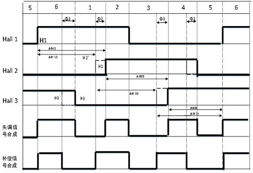
[0047] As shown in the figure, the present invention provides a permanent magnet synchronous motor Hall sensor fault-tolerant control method, such as Figure 4 shown, including the following steps:

[0048] Step S1: The permanent magnet synchronous motor is generally equipped with three symmetrically installed Hall sensors. The encoding signal generated by the three-phase Hall sensor can convert one electrical cycle of the permanent magnet synchronous motor (t...


PUM


Abstract

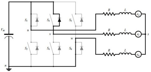
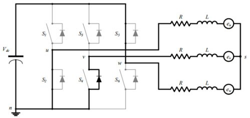
The invention belongs to the technical field of permanent magnet synchronous motor control, and particularly relates to a fault-tolerant control method for a Hall sensor of a permanent magnet synchronous motor, which comprises the following steps of: obtaining a position error calculation formula of a Hall sensor signal under the assumption of constant-speed operation; when an upper diode of the inverter is used for executing follow current operation, the phase commutation time of the motor is deduced according to the relation of parameters such as phase current and back electromotive force; when a lower diode of the inverter is used for executing follow current operation, phase change time is deduced according to the expression of the direct current bus voltage; deriving the optimal advance time and the optimal advance angle according to the commutation time of the two working states of the motor; the active lead angle of the Hall sensor compensation method is summarized, the defects in the prior art are overcome, the optimal angle for compensating the Hall sensor can be accurately estimated when the installation position of the Hall sensor is inaccurate, and the accuracy of motion of the permanent magnet synchronous motor is improved.

Description

technical field [0001] The invention belongs to the technical field of permanent magnet synchronous motor control, and in particular relates to a fault-tolerant control method of a hall sensor of a permanent magnet synchronous motor. Background technique [0002] The permanent magnet synchronous motor has many advantages such as simple structure, high power density, and simple control. In recent years, permanent magnet synchronous motors have been increasingly widely used in industrial fields such as high-performance speed regulation systems and servo control systems. [0003] Hall sensors in BLDC motors are ideally placed between 120 electrical degrees. However, the placement of Hall sensors can be inaccurate, especially in high precision and small size motors. These misadjusted Hall sensors cause severe torque ripple and are difficult to apply. [0004] Due to the absence of Hall sensors, a sensorless control scheme for BLDC motors is a good option to avoid Hall sensor ...

Claims


Application Information

Patent Timeline
Patent Type & Authority Applications(China)
IPC IPC(8): H02P6/16H02P6/15
CPCH02P6/16H02P6/15
Inventor 孟智超张懿王浩陈魏海峰
Owner JIANGSU UNIV OF SCI & TECH
Learn More