Eureka AIR delivers breakthrough ideas for toughest innovation challenges, trusted by R&D personnel around the world.

Press-fit jig and press-fit method

A technology for pressing jigs and pressing parts, applied in electrical components, printed circuit manufacturing, printed circuits, etc., can solve the problems of high labor costs, crushing circuit boards, and difficulty in controlling the size of the pressing force. The effect of reducing labor cost and improving pressing efficiency

Pending Publication Date: 2022-03-25
UNIVERSAL GLOBAL TECH KUNSHAN
View PDF0 Cites 0 Cited by
  • Summary
  • Abstract
  • Description
  • Claims
  • Application Information

AI Technical Summary

Problems solved by technology

[0003] At present, in the process of laminating the ball grid packaging circuit, it is usually necessary to manually complete multi-step operations such as scanning, discharging, pressing, and recording. The operation process is cumbersome and the labor cost is high.
On the other hand, in the process of manually controlling the pressing down of the jig, the amount of the pressing force is not easy to control, and it is easy to crush the circuit board or the insufficient pressing distance will cause poor contact between the jig and the circuit board.

Method used


Image

  • Press-fit jig and press-fit method
  • Press-fit jig and press-fit method
  • Press-fit jig and press-fit method

Examples


Embodiment Construction

[0040] In order to more clearly illustrate the embodiments of the present invention or the technical solutions in the prior art, the specific implementation manners of the present invention will be described below with reference to the accompanying drawings. Obviously, the accompanying drawings in the following description are only some embodiments of the present invention, and those skilled in the art can obtain other accompanying drawings based on these drawings and obtain other implementations.

[0041] In order to keep the drawings concise, each drawing only schematically shows the parts related to the invention, and they do not represent the actual structure of the product. In addition, to make the drawings concise and easy to understand, in some drawings, only one of the components having the same structure or function is schematically shown, or only one of them is marked. Herein, "a" not only means "only one", but also means "more than one".

[0042] It should also be...


PUM


Abstract

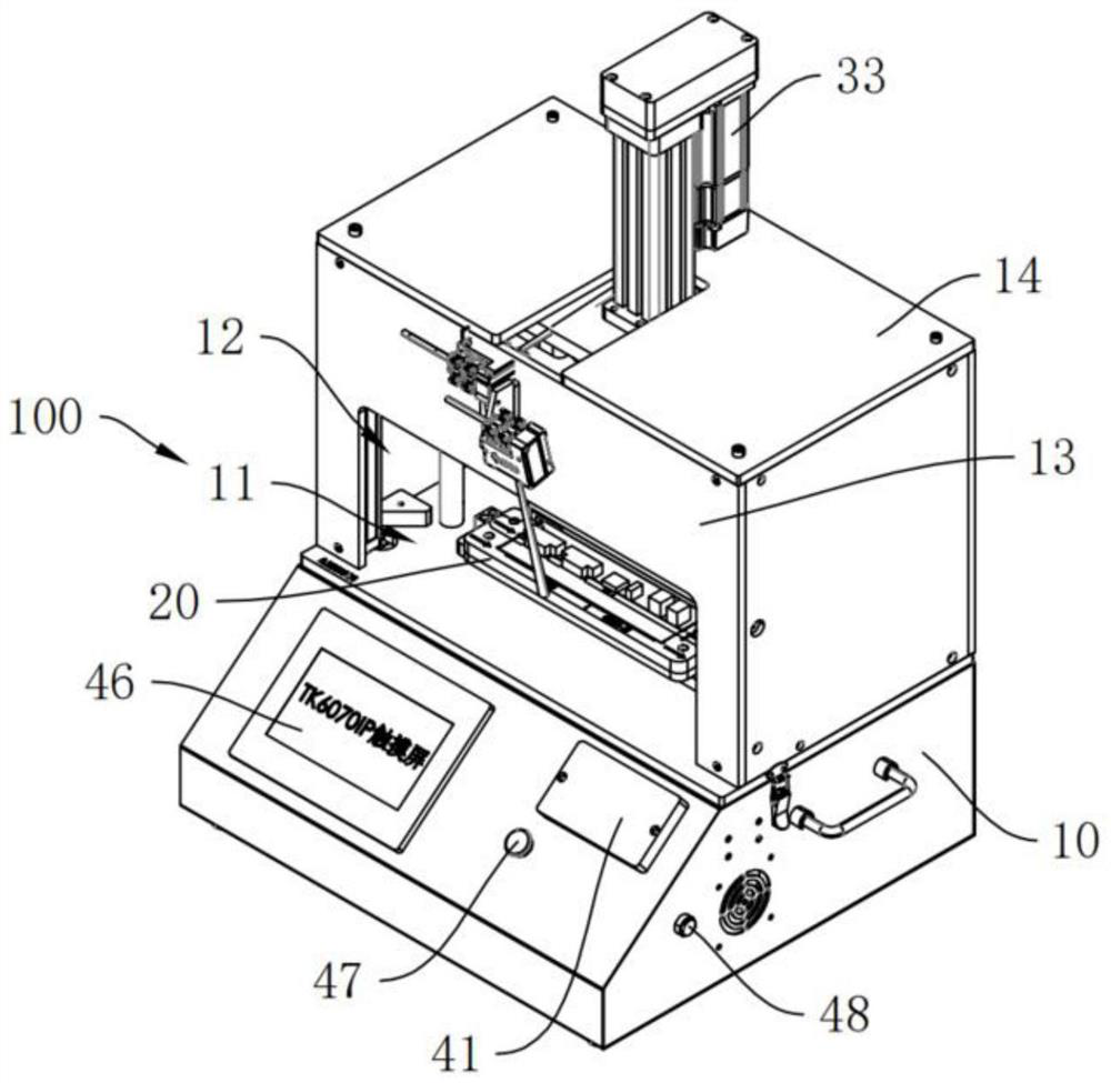
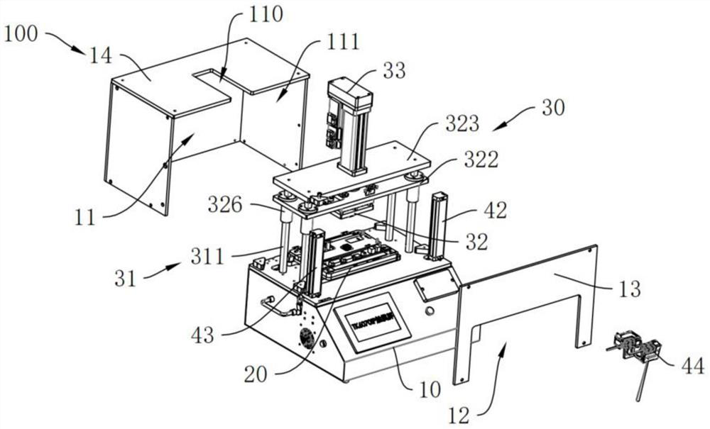
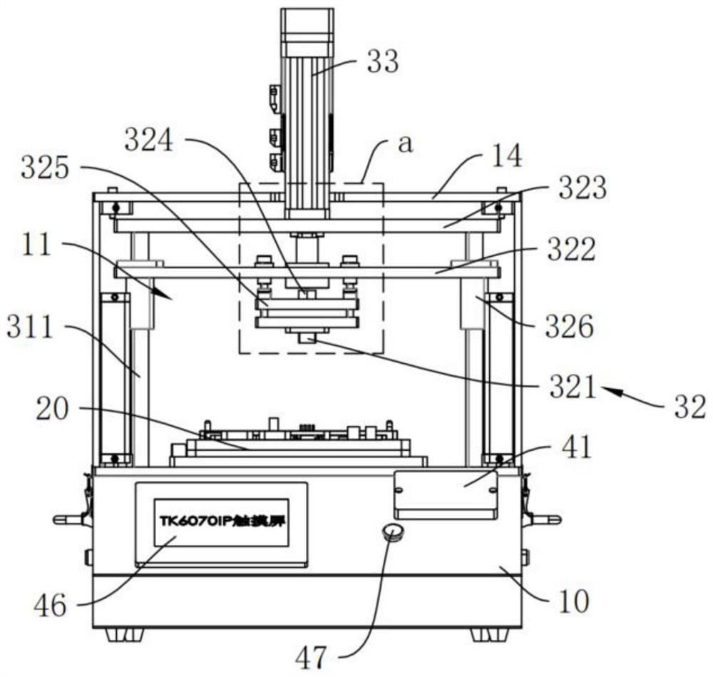
The invention discloses a press-fit jig and a press-fit method. The press-fit jig comprises a base; the pressing cavity is mounted on the base, and a pressing operation window is arranged on the operation surface of the pressing cavity; the bearing mechanism is located in the pressing cavity, placed on the base and used for bearing a part to be pressed; the pressing mechanism comprises a movable guide rail located in the pressing cavity, a pressing assembly and a driving part extending out of the top face of the pressing cavity, the movable guide rail is vertically installed on the base and arranged on the periphery of the bearing mechanism, and the pressing assembly is slidably installed on the movable guide rail and arranged on the top face of the pressing cavity. The driving part is connected to the pressing assembly and can drive the pressing assembly to move downwards along the movable guide rail so as to press the part to be pressed. The pressing head of the pressing assembly can be automatically controlled to ascend and descend without manual operation, the labor cost can be reduced, and the pressing efficiency is improved.

Description

technical field [0001] The invention relates to the field of pressing, and further relates to a pressing fixture and a pressing method. Background technique [0002] Ball grid package (BGA, Ball GridArray Package) is a new integrated circuit packaging technology that has emerged in recent years. It can increase the memory capacity to two to three times without changing the volume, and has a faster and more effective heat dissipation method. [0003] At present, in the process of laminating the ball grid packaging circuit, it is usually necessary to manually complete multi-step operations such as scanning, discharging, pressing, and recording. The operation process is cumbersome and the labor cost is high. On the other hand, in the process of manually controlling the pressing down of the jig, the pressing force is not easy to control, and it is easy to crush the circuit board or the insufficient pressing distance causes poor contact between the jig and the circuit board. It ...

Claims


Application Information

Patent Timeline
Patent Type & Authority Applications(China)
IPC IPC(8): H05K3/00
CPCH05K3/00
Inventor 范养桂林博彦梁衍坤朱熹图
Owner UNIVERSAL GLOBAL TECH KUNSHAN
Why Eureka
Eureka Blog
Learn More