Railway track fastening device

A fastening device and a technology of railway track, applied in the field of railway track, can solve the problems of inconvenient various terrains, weak fastening effect, inconvenient adjustment of the height of the railway track, etc., and achieve the effect of strengthening stability

Pending Publication Date: 2022-03-29
CHINA CIVIL ENG CONSTR CORP
View PDF1 Cites 0 Cited by
  • Summary
  • Abstract
  • Description
  • Claims
  • Application Information

AI Technical Summary

Problems solved by technology

[0006] The object of the present invention is to provide a railway track fastening device. Through the setting of the lifting mechanism and the setting of the first pressing plate and the second pressing plate, the existing railway track fastening device is solved. When fastening the railway track, the height of the railway track is constant. , it is not convenient to adjust the height of the rail, it is not convenient to apply to various terrains, and it is generally fastened by two fastening pieces on both sides, and the fastening effect is not strong.

Method used


Image

  • Railway track fastening device
  • Railway track fastening device
  • Railway track fastening device

Examples


Embodiment Construction

[0038] The technical solutions in the embodiments of the present invention will be apparent from the drawings in the embodiment of the present invention.

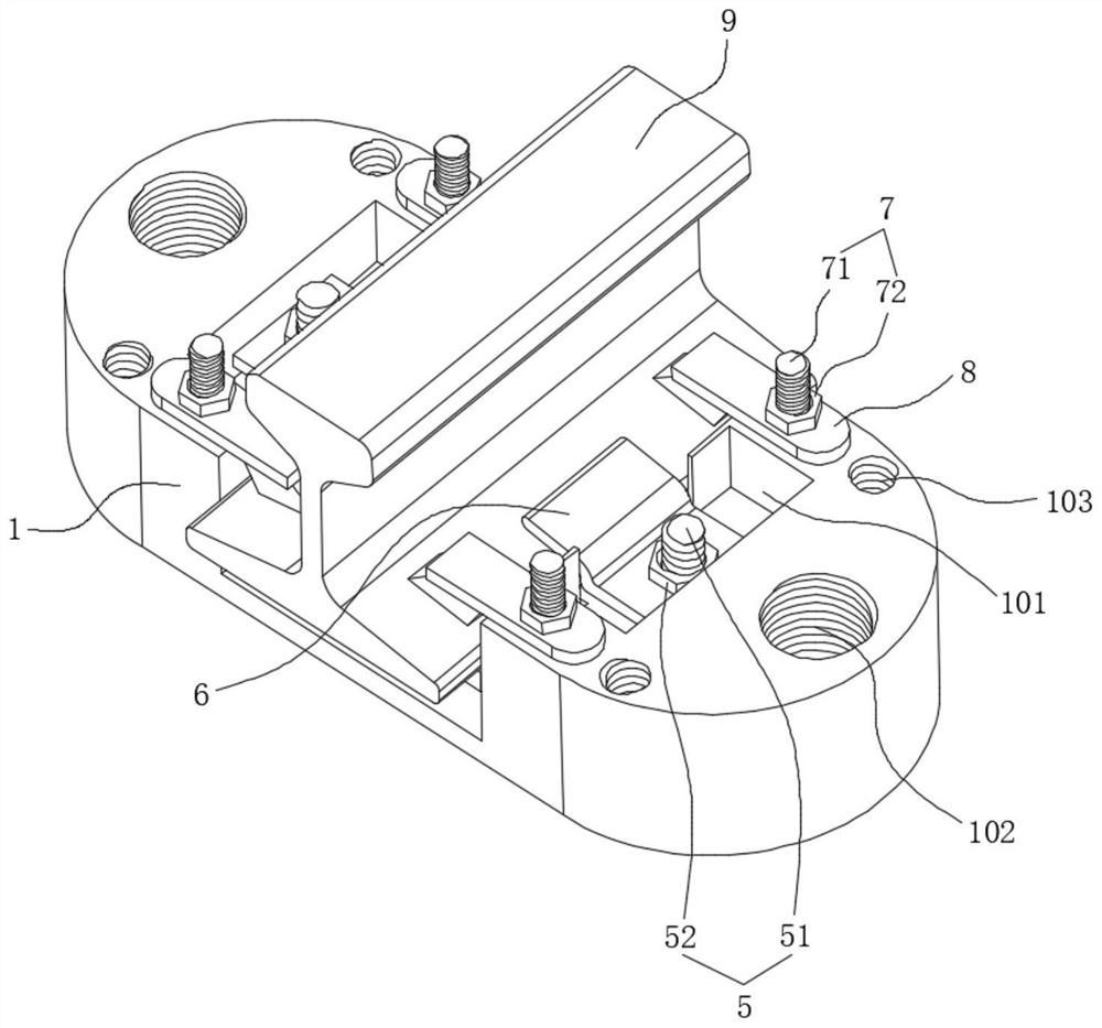
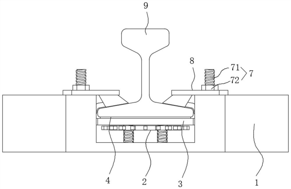
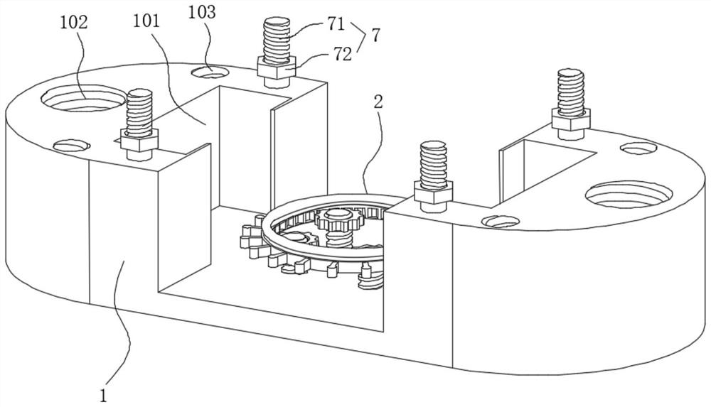
[0039] See Figure 2-3 , Figure 5-7 and Figure 10 As shown, the present invention is a railway track fastening device comprising a cast iron base 1, a lifting mechanism 2, a lifting plate 3, a rubber pad 4, a first adjustment structure 5, a first pressure plate 6, a second adjustment structure 7, and The second pressure plate 8 and the rail 9 are fixed at the intermediate groove at the cast iron base 1, and the lifting mechanism 2 includes an internal gear 21, a threaded rod 22, a handle 23, a handle 24, and a ring slide rail 25, and adjusts the peripheral side of the handle 23. The handle 24 is provided, and the handle 24 is welded. The top welding of the adjustment handle 23 is welded, and the internal engagement of the adjustment handle 23 has a set of symmetrical arranged internal gear 21, each inner gear 21 is set and threa...


PUM


Abstract

The invention discloses a railway track fastening device, and relates to the technical field of rail tracks. The device comprises a cast iron base, a lifting mechanism, a first pressing plate, a second pressing plate and a rail, the lifting mechanism is fixed to a groove in the middle of the cast iron base, the lifting mechanism comprises inner gears, threaded rods, an adjusting handle, a handle and an annular sliding rail, and each inner gear sleeves and is in threaded connection with the corresponding threaded rod; the bottom of each threaded rod is fixed to a middle groove of the cast iron base, the top of the lifting mechanism is movably connected with a lifting plate, and the two ends of the lifting plate are slidably connected with the cast iron base. The rail is placed on the whole of the lifting mechanism, the lifting plate and the rubber cushion plate in the groove in the middle of the cast iron base and pressed and fastened through the first pressing plate and the second pressing plate on the two sides of the groove in the middle of the cast iron base. The lifting mechanism is arranged, in the using process, the lifting plate can be moved upwards or downwards through the lifting mechanism, the height of the lifting plate can be properly adjusted for use according to the terrain requirement, and the lifting device can be suitable for different terrains.

Description

Technical field [0001] The present invention belongs to the field of rail rails, and more particularly to a railway track fastening device. Background technique [0002] At present, there is a railway fastening device in the railway pillow, and the rails are fastened by the fastening device. CN201428095Y - a railway track fastening device, is disclosed, a bomb, iron pad , The bomb bolt and iron pad bolt of the iron pads; the iron pad bolt is characterized, and there is a rubber pad, and the rubber pad is provided, and the groove is provided in the groove in the groove. The insulating block is on one side of the rail rail, and the shape of the outer portion of the rail rail and the lower portion of the rail, the bomb is extruded under the main pressure of the bollar bolt under the insulating block. On both sides of the iron pad, the bomb strip mounting bracket is provided around the bomb bolt hole, and the bomb mounting holder is close to the side of the insulating block on one si...

Claims


Application Information

Patent Timeline
IPC IPC(8): E01B9/54E01B9/58
CPCE01B9/54E01B9/58
Inventor 康伟周义海振瑾
Owner CHINA CIVIL ENG CONSTR CORP
Why Eureka
Try Eureka