Display panel

A display panel and display area technology, applied in static indicators, organic semiconductor devices, instruments, etc., can solve problems such as short circuit of test pads in CT test area, solve short circuit between test pads, reduce the probability of short circuit, The effect of increasing the interval

Pending Publication Date: 2022-03-29
WUHAN CHINA STAR OPTOELECTRONICS TECH CO LTD
View PDF20 Cites 1 Cited by
  • Summary
  • Abstract
  • Description
  • Claims
  • Application Information

AI Technical Summary

Problems solved by technology

[0003] The present application provides a display panel to alleviate the technical proble...

Method used


Image

  • Display panel
  • Display panel
  • Display panel

Examples


Embodiment Construction

[0024] The following descriptions of the various embodiments refer to the accompanying drawings to illustrate specific embodiments that the present application can be used to implement. The directional terms mentioned in this application, such as [top], [bottom], [front], [back], [left], [right], [inside], [outside], [side], etc., are for reference only The orientation of the attached schema. Therefore, the directional terms used are used to illustrate and understand the application, but not to limit the application. In the figures, structurally similar elements are denoted by the same reference numerals. In the drawings, the thicknesses of some layers and regions are exaggerated for clear understanding and ease of description. That is, the size and thickness of each component shown in the drawings are arbitrarily shown, but the present application is not limited thereto.

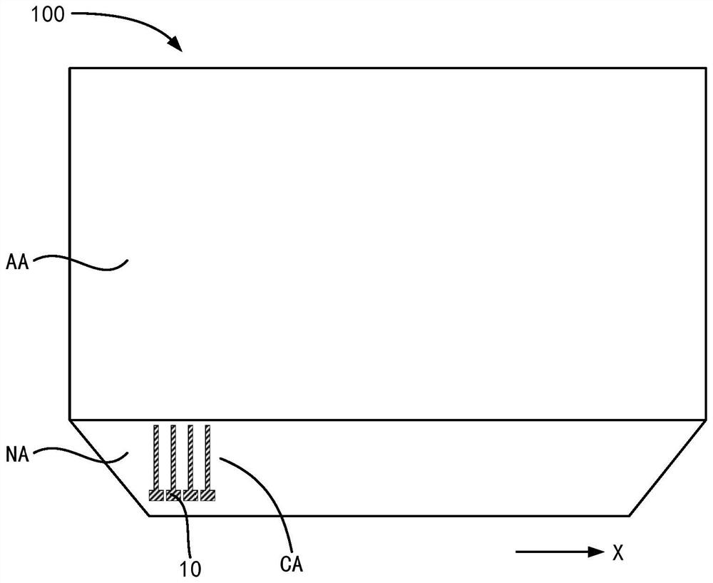
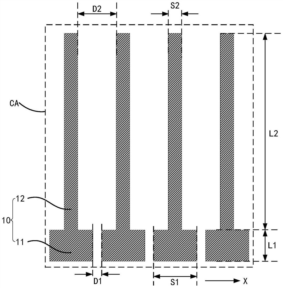
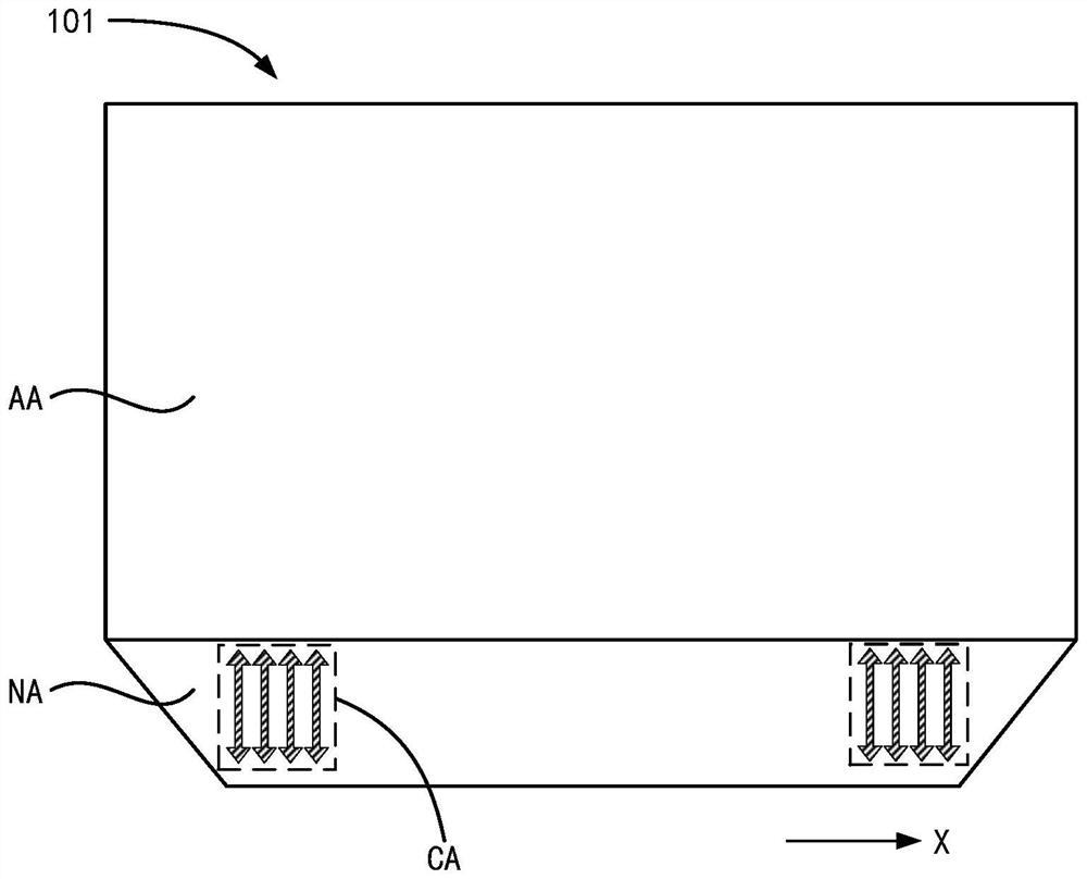
[0025] Aiming at the problem of short circuit between the test pads in the CT test area existing in t...


PUM

PropertyMeasurementUnit
Widthaaaaaaaaaa

Abstract

The invention provides a display panel which comprises a display area and a non-display area located on one side of the display area, at least one test area is arranged in the non-display area, and each test area comprises a plurality of test terminals arranged in the non-display area in an array mode in the first direction. Each test terminal comprises a first test part and a second test part electrically connected with the first test part, the width of the first test part along the first direction is greater than the width of the second test part along the first direction, and the first test part is used as a test contact point, so that the test efficiency is improved on the premise of ensuring the width of the test contact point on the test terminal. The width of other positions on the test terminals is reduced, so that the interval between the adjacent test terminals is increased, the probability of short circuit between the adjacent test terminals is further reduced, and the problem of short circuit between test connecting pads in a CT test area of an existing display panel is solved.

Description

technical field [0001] The present application relates to the field of display technology, and in particular to a display panel. Background technique [0002] With the development of display technology, display products with high screen-to-body ratio have become the mainstream in the market, and an effective way to achieve high screen-to-body ratio is to use narrow bezel technology to reduce the bezel of display products. However, the narrow frame design will inevitably compress the space of some functional areas on the frame, such as the Cell Test test area (ie, the CT test area). The CT test area is designed with a test pad (CT pad), which is mainly used to provide signals to the test pad through the fixture after the display panel of the display product is completed, and the test pad transmits the signal to the signal line in the display panel. In this way, it is detected whether there is a picture defect in the display panel, so as to detect the defect in time. However...

Claims


Application Information

Patent Timeline
IPC IPC(8): G09G3/00H01L51/52H01L27/32
CPCG09G3/006H10K59/00H10K50/80H10K2102/341
Inventor 孙彬
Owner WUHAN CHINA STAR OPTOELECTRONICS TECH CO LTD
Why Eureka
Try Eureka