Inertia-based magnetic locking type switch

A latching, magnetic technology, applied in electrical switches, weapon accessories, direction control systems, etc., can solve problems such as unreliable work, turbine work effectiveness, data loss, etc., and achieve the effect of simplifying structure layout and improving stability

Active Publication Date: 2022-03-29
HUNAN MAXWELL ELECTRONICS TECH
View PDF4 Cites 0 Cited by
  • Summary
  • Abstract
  • Description
  • Claims
  • Application Information

AI Technical Summary

Problems solved by technology

If the circuit is turned on too late, it will cause data loss during launch and flight, and it will be impossible to accurately detect the target and achieve the intended function
It is also possible to use turbine

Method used


Image

  • Inertia-based magnetic locking type switch
  • Inertia-based magnetic locking type switch
  • Inertia-based magnetic locking type switch

Examples


Embodiment Construction

[0023] In order to make the object, technical solution and advantages of the present invention clearer, the present invention will be further described in detail below in conjunction with the accompanying drawings and embodiments. It should be understood that the specific embodiments described here are only used to explain the present invention, not to limit the present invention. The various specific technical features and various embodiments described in the specific implementation manners can be combined in any suitable manner if there is no contradiction. For example, different specific technical features / embodiments can be combined to form different implementations. In order to avoid unnecessary repetition, various possible combinations of specific technical features / embodiments in the present invention will not be further described.

[0024] It should be noted that the terms "setting" and "connection" should be understood in a broad sense, for example, they can be direct...


PUM


Abstract

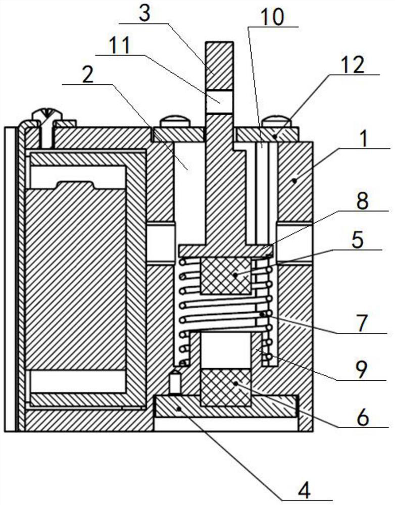
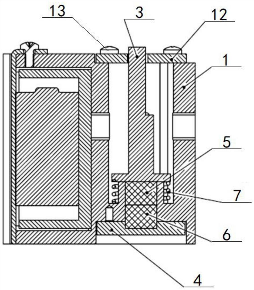
The invention provides an inertia-based magnetic locking type switch, which comprises a shell, a conducting hole is formed in the shell, a first connecting column is movably arranged at the first end of the conducting hole, a second connecting column is fixedly arranged at the second end of the conducting hole, and circuit conduction is completed when the power connection end of the first connecting column is in contact with the power connection end of the second connecting column. The first connecting column is elastically connected with the shell, the first connecting column overcomes the elastic force to do work under the action of inertia force to make contact with the second connecting column, the power connection end of the first connecting column and the power connection end of the second connecting column are provided with a first magnet and a second magnet respectively, and the first magnet and the second magnet can conduct electricity. The first magnet and the second magnet are fixed through magnetic attraction, time delay does not need to be set in advance in a program, locking can be formed through magnetic attraction force after conduction, the conduction state is maintained, the conduction stability and the accuracy and reliability of test data collection are improved, and meanwhile the structural arrangement is simplified.

Description

technical field [0001] The invention relates to the technical field of latching switches, in particular to an inertia-based magnetic latching switch. Background technique [0002] In the early stage of research and development, the initial performance test of the detector is usually carried out by the simulated projectile launch test. This method not only requires less manpower and material resources, but also can complete the rapid test. The external environment and other objective factors are comprehensively considered, and the test results are more credible and reliable. For safety reasons, the entire circuit of the detector of the dummy bomb is disconnected when it leaves the factory, because if the detector part is powered on at the beginning, the product may detect non-target objects at any time and output corresponding signals and commands. However, in order to satisfy the function, it is also required that the dummy bullet can be powered on and conducted when it is e...

Claims


Application Information

Patent Timeline
IPC IPC(8): H01H3/16H01H9/20F41G7/00
CPCH01H3/16H01H9/20F41G7/001Y02E60/16
Inventor 李辉穆雪峰
Owner HUNAN MAXWELL ELECTRONICS TECH
Why Eureka
Try Eureka