Feeding mechanism for metal machining and manufacturing

A metal processing and workbench technology, which is applied in the field of processing and manufacturing, can solve the problems of different lengths of steel pipes and affect the cutting quality, and achieve the effect of improving accuracy and ensuring uniformity.

Active Publication Date: 2022-04-01
常德市鼎城区正荣机械制造有限公司
View PDF13 Cites 4 Cited by
  • Summary
  • Abstract
  • Description
  • Claims
  • Application Information

AI Technical Summary

Problems solved by technology

[0004] In order to make up for the deficiencies of the existing technology, it is necessary to solve the problem that steel pipes need to be cut evenly in sections for use. However, when the steel pipes are cut in sections, when the steel pipes are artificially pushed to move and cut, not only will the length of the steel pipe sections be different, but it will also affect the The problem of cutting quality, a kind of feeding mechanism for metal processing and manufacturing proposed by the present invention

Method used


Image

  • Feeding mechanism for metal machining and manufacturing
  • Feeding mechanism for metal machining and manufacturing
  • Feeding mechanism for metal machining and manufacturing

Examples


Embodiment 1

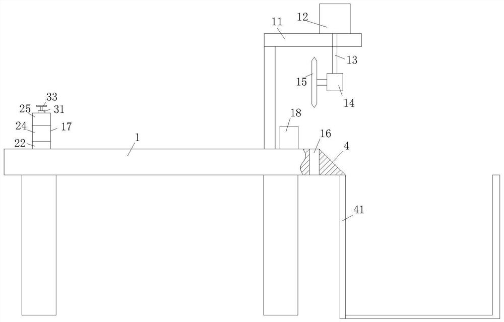
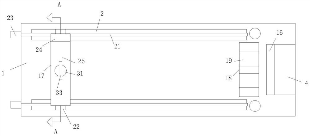
[0025] Such as Figure 1 to Figure 5 As shown, a feeding mechanism for metal processing and manufacturing according to the present invention includes a workbench 1; a fixed plate 11 is fixedly connected to the workbench 1 through a fixed column; a hydraulic cylinder is fixedly connected to the top of the fixed plate 11 12. The output end of the bottom end of the hydraulic cylinder 12 is provided with a hydraulic rod 13; the bottom end of the hydraulic rod 13 is fixedly connected with a first motor 14; the first motor 14 is fixedly connected with a cutting wheel 15 through a first rotating shaft; The position of the workbench 1 relative to the cutting wheel 15 is provided with a first through groove 16; the position of the workbench 1 close to the first through groove 16 is fixedly connected with a placement seat 18; the placement seat 18 is provided with a A group of first grooves 19; the power unit on the workbench 1 drives the first fixed seat 17 to move on the workbench 1; ...

Embodiment 2

[0033] Such as Figure 6 As shown in Comparative Example 1, as another embodiment of the present invention, a group of fourth grooves 44 are provided on the side wall of the locking block 42; the inner wall of the fourth groove 44 is fixed with a Roller 45; during work, a fourth groove 44 is provided on the side wall of the clamping block 42, and a roller 45 is provided in the fourth groove 44. When a pair of clamping blocks 42 limit the steel pipe, the roller 45 is passed. The frictional force between the clamping block 42 and the steel pipe can be reduced, and the horizontal movement of the water inlet of the steel pipe can be facilitated.

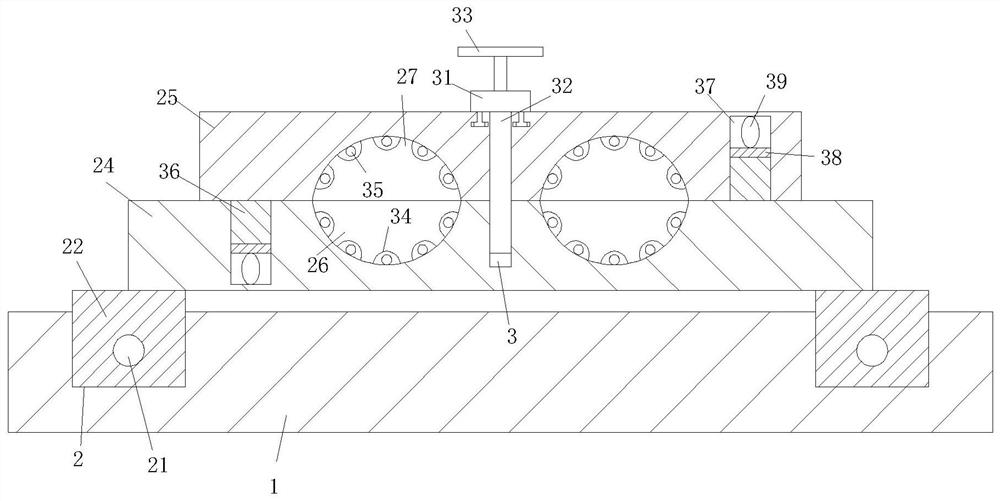
[0034] Working principle: When the steel pipe needs to be cut in sections, place the steel pipe of the required length between the first arc groove 26 and the second arc groove 27, place the threaded rod 32 on the threaded rod 32, and then pass the T The shape column rotates the turntable 31, and then drives the threaded rod 32 to rotat...


PUM


Abstract

The invention belongs to the technical field of machining and manufacturing, and particularly relates to a feeding mechanism for metal machining and manufacturing. The workbench is fixedly connected with a fixing plate through a fixing column. The top end of the fixed plate is fixedly connected with a hydraulic cylinder; a hydraulic rod is arranged at the output end of the bottom end of the hydraulic cylinder; the bottom end of the hydraulic rod is fixedly connected with a first motor; the first motor is fixedly connected with a cutting wheel through a first rotating shaft; a first through groove is formed in the position, opposite to the cutting wheel, of the workbench. A placing seat is fixedly connected to the position, close to the first through groove, of the workbench. A group of first grooves are formed in the placing seat; according to the feeding mechanism for metal machining and manufacturing, the problems that steel pipes need to be cut in a uniform segmentation mode for use, but when the steel pipes are cut in a segmentation mode and manually pushed to move and cut, the segmentation lengths of the steel pipes are different, and the cutting quality is affected are solved.

Description

technical field [0001] The invention belongs to the technical field of processing and manufacturing, in particular to a feeding mechanism for metal processing and manufacturing. Background technique [0002] In the production process of the steel pipe, the steel pipe needs to be cut into sections for use, and a cutting machine is generally used to cut into sections during cutting. [0003] In the prior art, the steel pipe needs to be cut evenly in sections for use, but when the steel pipe is cut in sections, when the steel pipe is artificially pushed to move and cut, not only will the length of the steel pipe sections be different, but also the cutting quality will be affected. Therefore, the present invention provides a feeding mechanism for metal processing and manufacturing. Contents of the invention [0004] In order to make up for the deficiencies of the existing technology, it is necessary to solve the problem that steel pipes need to be cut evenly in sections for u...

Claims


Application Information

Patent Timeline
Patent Type & Authority Applications(China)
IPC IPC(8): B23D47/02B23D47/04B23D47/10B23Q7/00B23Q7/08B23Q7/10
Inventor 代亚烽陈广周强唐金
Owner 常德市鼎城区正荣机械制造有限公司
Why Eureka
Try Eureka