Device and method for blocking pipeline under pressure without stopping conveying and moving fire

A technology for pipelines and plugging holes, applied in the direction of pipe elements, pipes/pipe joints/pipe fittings, mechanical equipment, etc., can solve the problems of inability to weld large currents, limitations of technical environmental factors, failure of plugging under pressure, etc., and achieve the construction process. handy effect

Pending Publication Date: 2022-04-01
新疆润霖新能源技术有限公司
View PDF6 Cites 0 Cited by
  • Summary
  • Abstract
  • Description
  • Claims
  • Application Information

AI Technical Summary

Problems solved by technology

The technology itself is limited by environmental factors
② During the non-stop pipeline welding operation, the prefabricated parts and the pipe body itself cannot be welded with high current when the pipeline is welded under pressure, so the welding quality of the prefabricated parts and the pipeline cannot be guaranteed, and there is a risk of leakage
③The sealing head under pressure in the pipeline is mostly sealed with rubber, and the seal is plastically deformed by manual, mechanical extrusion or hydraulic power to realize the sealing under pressure. However, during the operation of the pipeline, due to the internal structure of the pipeline, the material Corrosion, material carrying sediment and impurities, etc., cause the inner wall of the pipeline to be irregular, and in the process of sealing under pressure, local sealing is not tight, resulting in the failure of sealing under pressure and affecting the success rate

Method used


Image

  • Device and method for blocking pipeline under pressure without stopping conveying and moving fire
  • Device and method for blocking pipeline under pressure without stopping conveying and moving fire
  • Device and method for blocking pipeline under pressure without stopping conveying and moving fire

Examples


Embodiment Construction

[0037] The principles and features of the present invention are described below in conjunction with the accompanying drawings, and the examples given are only used to explain the present invention, and are not intended to limit the scope of the present invention.

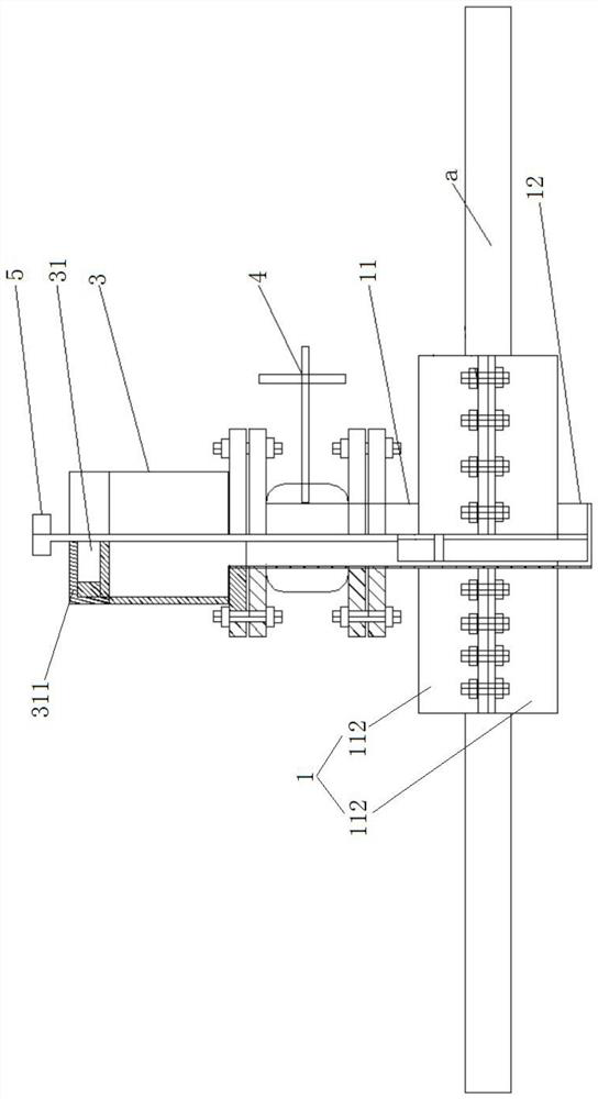
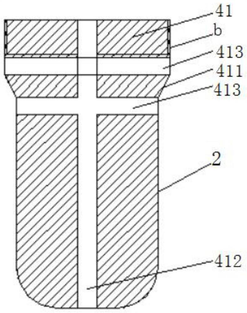
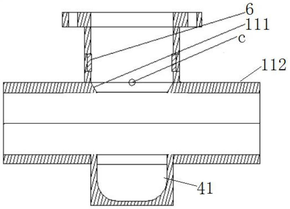
[0038] Example: such as figure 1 , 2 As shown in , 3, the device for non-stop pipeline non-fired and pressure plugging of the present embodiment includes an outer plugging pipe 1, an inner sealing body 2, a plugging working cylinder 3 and a valve 4, and the above-mentioned outer plugging pipe 1 is used for The sealing sleeve is set outside the pipeline plugging point, and the middle parts of both sides are respectively coaxially provided with plugging holes 111, and the outer periphery of one of the above-mentioned plugging holes 111 is sealed with a connecting pipe 11 perpendicular to the above-mentioned outer plugging pipe 1, The outside of another one of the above-mentioned plugging holes 111 is sealed with an i...


PUM


Abstract

The invention relates to a device and a method for blocking a pipeline under pressure without stopping conveying and moving fire. The device comprises an outer plugging pipe, an inner sealing body, a plugging working barrel and a valve, the outer plugging pipe is used for sleeving a pipeline plugging point in a sealing mode, plugging holes are coaxially formed in the middles of the two sides of the outer plugging pipe respectively, and a connecting pipe perpendicular to the outer plugging pipe is assembled on the periphery of the outer side of one plugging hole in a sealing mode; a hollow sealing bin is assembled on the periphery of the outer side of the other plugging hole in a sealed mode, one valve port of the valve is assembled with a pipe port of the connecting pipe in a sealed mode, the plugging working barrel is detachably assembled at the position of the other valve port of the valve in a sealed mode, and the inner sealing body is arranged in the plugging working barrel. A pushing structure detachably connected with one end of the inner sealing body is arranged in the plugging working barrel, and a sealing structure in sealed connection with the inner wall of a pipeline plugging point is arranged outside the inner sealing body. The method has the advantages that fire-free under-pressure operation is achieved during whole-course construction, and potential safety hazards are reduced.

Description

technical field [0001] The invention relates to the technology of pipeline sealing under pressure, in particular to a device and method for pipeline under pressure sealing without stoppage or fire. Background technique [0002] Pipeline non-stop transmission with pressure plugging is a relatively common pipeline construction and maintenance method for emergency maintenance of process technology. There are two technical shortcomings in the existing hot plugging process: ① Hot plugging requires prefabricated hot plugging device pipe fittings to be welded to the pipeline to be plugged by welding. Welding operations are carried out without stopping production in flammable and explosive areas, and the risk of fire and explosion is high, which can easily cause fire and explosion, and induce safety accidents. The technology itself is limited by environmental factors. ②During the non-stop pipeline welding operation, the prefabricated parts and the pipe body itself cannot be welded...

Claims


Application Information

Patent Timeline
Patent Type & Authority Applications(China)
IPC IPC(8): F16L55/1645F16L55/17
Inventor 史涛
Owner 新疆润霖新能源技术有限公司
Why Eureka
Try Eureka