Reliefable Double Lock Blowout Mandrel
A technology of working cylinder and blowout prevention, which is applied in the direction of wellbore/well valve device, wellbore/well parts, sealing/isolation, etc., which can solve the problems that well fluid pollution is difficult to avoid completely, and achieve the effect of ensuring reliability
- Summary
- Abstract
- Description
- Claims
- Application Information
AI Technical Summary
Problems solved by technology
Method used
Image
Examples
Embodiment 1
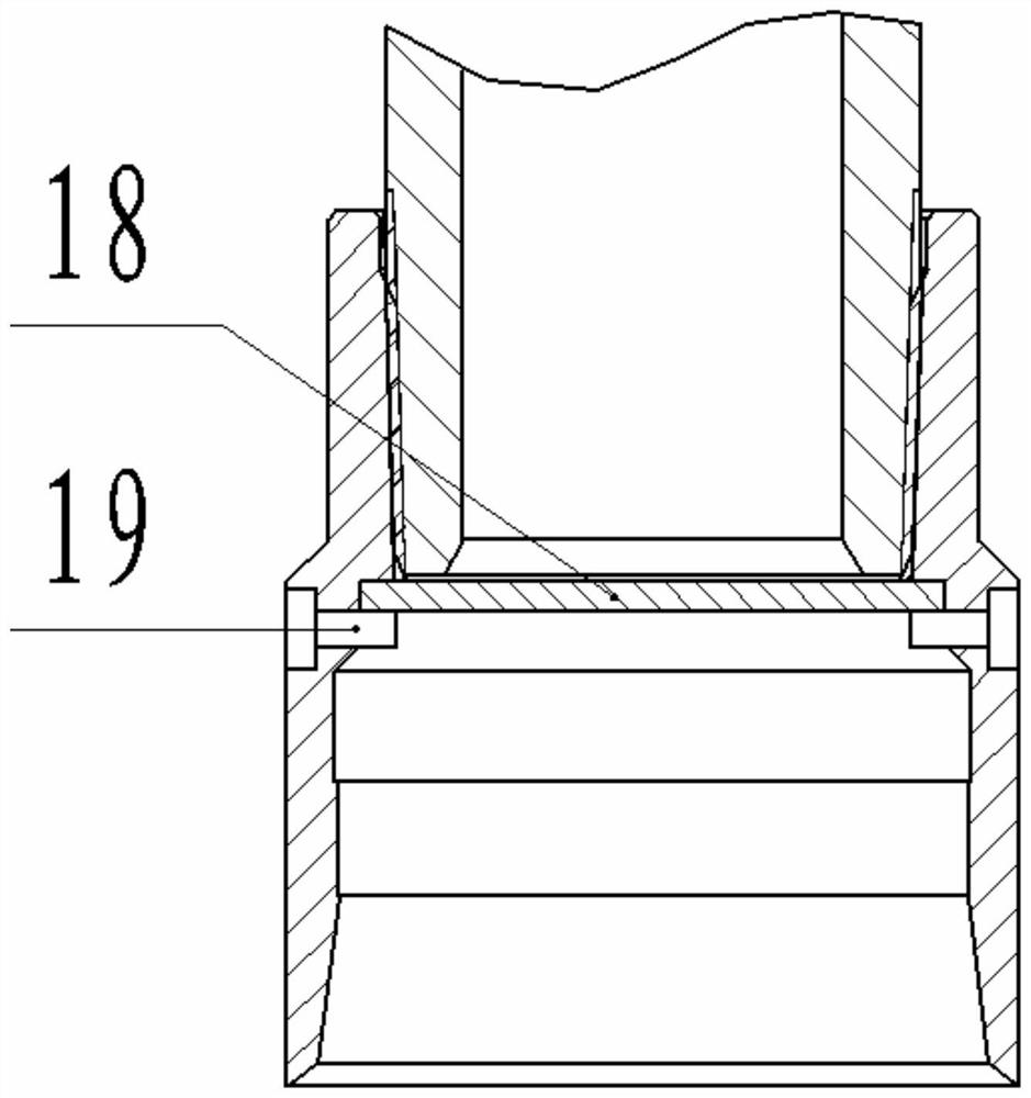
[0052] Such as image 3 As shown, the blocking device includes a baffle plate 18 and a shear nail 19, the upper side of the baffle plate 18 is limited by the stop on the inner side of the lower joint 5, and the lower side of the baffle plate 18 is limited by the baffle plate 18 installed on the side wall of the lower joint 5. Scissors 19 limit. Before the oil pumping operation, take a metal rod as a casting rod, put the casting rod into the pipe string for unblocking, the casting rod hits the baffle plate 18, the shear nail 19 is cut off, the baffle plate 18 and the casting rod fall to the bottom of the artificial well, and pass through Blocking job done. The material of the casting rod can be made of lead or tungsten with higher density.
[0053] The advantage of this embodiment is that the structure is simple and the operation is convenient. The disadvantage is that the pipe string cannot withstand too high pressure (the shear pin 19 will be cut off if the pressure is too ...
Embodiment 2
[0055] Such as Figure 4 and Figure 5 As shown, as a further technical solution, the blocking device includes a ball seat 20, an unlocking ball 22, a sliding pin 24, a sliding block 23, a spring A21 and a spring B25, and on the side wall of the ball seat 20 and the lower joint 5 A radial through hole is provided, and the spring B25, the sliding block 23 and the sliding pin 24 are all installed in the radial through hole, wherein the sliding pin 24 is slidably installed on the ball seat 20, and the sliding block 23 is mounted on the spring B25. Under the action of elastic force, it always leans against the end surface of the sliding pin 24. The ball seat 20 is provided with a ball groove matching the unlocking ball 22. When the unlocking ball 22 falls into the ball groove, the sliding pin 24 is in the process of unlocking the ball. 22 to slide along its own axial direction, when the unlocking ball 22 falls on the bottom of the ball groove, the fitting surface between the slid...
Embodiment 3
[0060] Such as Figure 6 As shown, as a further technical solution, the blocking device includes a seal seat 27, a piston 26 and a lock pin 28, the piston 26 is installed in the blind hole in the center of the seal seat 27 from the upper side, and the side wall of the seal seat 27 A radial through hole is processed on the top, and the lock pin 28 is inserted into the radial through hole. An annular groove matching the lock pin 28 is processed on the inner wall of the lower joint 5, and one end of the lock pin 28 is inserted into the radial through hole. In the annular groove, the other end of the lock pin 28 is against the outside of the piston 26;
[0061] Two sealing rings 14 are arranged on the sealing surface between the piston 26 and the sealing seat 27, and a balance passage 33 is processed in the body of the sealing seat 27, and one end of the balance passage 33 leads to the two sealing rings 14 on the outside of the piston 26 Between, the other end of balance channel ...
PUM
 Abstract
Description
Claims
Application Information
 - R&D
- Intellectual Property
- Life Sciences
- Materials
- Tech Scout
- Unparalleled Data Quality
- Higher Quality Content
- 60% Fewer Hallucinations
Browse by: Latest US Patents, China's latest patents, Technical Efficacy Thesaurus, Application Domain, Technology Topic, Popular Technical Reports.
© 2025 PatSnap. All rights reserved.Legal|Privacy policy|Modern Slavery Act Transparency Statement|Sitemap|About US| Contact US: help@patsnap.com


