Decompressing double-lock blowout prevention working barrel

A work tube and blowout prevention technology, which is used in wellbore/well valve devices, wellbore/well components, earth-moving drilling and production, etc., can solve problems such as difficult to avoid well fluid pollution

Active Publication Date: 2020-10-20
大庆金祥寓科技有限公司
View PDF6 Cites 2 Cited by
  • Summary
  • Abstract
  • Description
  • Claims
  • Application Information

AI Technical Summary

Problems solved by technology

However, the disadvantages of this anti-pollution solution are: 1. The collected well fluid needs to be stored in a separate reservoir or tank, and a vehicle needs to be equipped for transportation; 2. The well fluid that reaches the well will inevitably be sprinkled in a small amount On the ground, so the pollution of the well fluid to the ground is difficult to completely avoid

Method used


Image

  • Decompressing double-lock blowout prevention working barrel
  • Decompressing double-lock blowout prevention working barrel
  • Decompressing double-lock blowout prevention working barrel

Examples


Embodiment 1

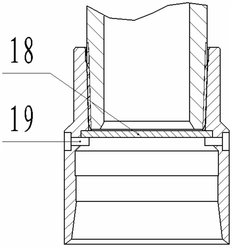
[0052] Such as image 3 As shown, the blocking device includes a baffle plate 18 and a shear nail 19, the upper side of the baffle plate 18 is limited by the stop on the inner side of the lower joint 5, and the lower side of the baffle plate 18 is limited by the baffle plate 18 installed on the side wall of the lower joint 5. Scissors 19 limit. Before the oil pumping operation, take a metal rod as a casting rod, put the casting rod into the pipe string for unblocking, the casting rod hits the baffle plate 18, the shear nail 19 is cut off, the baffle plate 18 and the casting rod fall to the bottom of the artificial well, and pass through Blocking job done. The material of the casting rod can be made of lead or tungsten with higher density.

[0053] The advantage of this embodiment is that the structure is simple and the operation is convenient. The disadvantage is that the pipe string cannot withstand too high pressure (the shear pin 19 will be cut off if the pressure is too ...

Embodiment 2

[0055] Such as Figure 4 and Figure 5 As shown, as a further technical solution, the blocking device includes a ball seat 20, an unlocking ball 22, a sliding pin 24, a sliding block 23, a spring A21 and a spring B25, and on the side wall of the ball seat 20 and the lower joint 5 A radial through hole is provided, and the spring B25, the sliding block 23 and the sliding pin 24 are all installed in the radial through hole, wherein the sliding pin 24 is slidably installed on the ball seat 20, and the sliding block 23 is mounted on the spring B25. Under the action of elastic force, it always leans against the end surface of the sliding pin 24. The ball seat 20 is provided with a ball groove matching the unlocking ball 22. When the unlocking ball 22 falls into the ball groove, the sliding pin 24 is in the process of unlocking the ball. 22 to slide along its own axial direction, when the unlocking ball 22 falls on the bottom of the ball groove, the fitting surface between the slid...

Embodiment 3

[0060] Such as Figure 6 As shown, as a further technical solution, the blocking device includes a seal seat 27, a piston 26 and a lock pin 28, the piston 26 is installed in the blind hole in the center of the seal seat 27 from the upper side, and the side wall of the seal seat 27 A radial through hole is processed on the top, and the lock pin 28 is inserted into the radial through hole. An annular groove matching the lock pin 28 is processed on the inner wall of the lower joint 5, and one end of the lock pin 28 is inserted into the radial through hole. In the annular groove, the other end of the lock pin 28 is against the outside of the piston 26;

[0061] Two sealing rings 14 are arranged on the sealing surface between the piston 26 and the sealing seat 27, and a balance passage 33 is processed in the body of the sealing seat 27, and one end of the balance passage 33 leads to the two sealing rings 14 on the outside of the piston 26 Between, the other end of balance channel ...


PUM


Abstract

The invention discloses a decompressing double-lock blowout prevention working barrel and relates to the technical field of oilfield borehole operation. The decompressing double-lock blowout prevention working barrel comprises a working barrel assembly; the working barrel assembly comprises a one-way valve, a collar, a barrel body, a sealing pipe and a lower joint sequentially connected through threads from top to bottom; the one-way valve structurally comprises a valve body and a valve ball; a valve hole is formed in the side wall of the valve body; the axial direction of the valve body is along the diameter direction of the valve body; the valve ball is mounted in the valve hole; under the elastic force action of a spring, the valve ball always keeps the moving trend close to the axis ofa valve seat to block the valve hole; and an upper annular clamping part and a lower annular clamping part are processed on the inner wall of the barrel body. The decompressing double-lock blowout prevention working barrel is applied to oil well pipe column bailing operation; when a pipe column is descended and ascended, a blanking plug assembly is put in a well to be in clamp joint with the working barrel assembly preassembled in the well so as to block a passage in the center of the pipe column, and the problem that well fluid in the pipe column overflows to the wellhead due to excessivelyhigh pressure of well fluid in a casing is prevented.

Description

technical field [0001] The invention belongs to the technical field of downhole operations in oil fields, and in particular relates to a pressure-releasing double-lock blowout prevention working cylinder. Background technique [0002] During the downhole operation in the oil field, when the pipe string is lowered and pulled out, due to the high pressure of the well fluid in the casing, the well fluid in the pipe string often overflows to the wellhead, causing environmental pollution on the well site. In order to solve the problem of the pollution of the well site environment, the technicians designed a wellhead liquid collection device to avoid environmental pollution by collecting the overflowed well fluid. However, the disadvantages of this anti-pollution solution are: 1. The collected well fluid needs to be stored in a separate reservoir or tank, and a vehicle needs to be equipped for transportation; 2. The well fluid that reaches the well will inevitably be sprinkled in ...

Claims


Application Information

Patent Timeline
Patent Type & Authority Applications(China)
IPC IPC(8): E21B33/12E21B34/08
CPCE21B33/12E21B34/08
Inventor 禹栽星黄国全谢冀江李长青宋波张国杰徐文超
Owner 大庆金祥寓科技有限公司
Why Eureka
Try Eureka