Anti-sparking circuit and power supply

A technology of ignition circuit and power supply, which is applied in the direction of circuit devices, emergency protection circuit devices, electrical components, etc., and can solve problems such as ignition

Active Publication Date: 2022-06-21
万灵帮桥医疗器械(广州)有限责任公司
View PDF9 Cites 0 Cited by
  • Summary
  • Abstract
  • Description
  • Claims
  • Application Information

AI Technical Summary

Problems solved by technology

[0003] The main purpose of this application is to provide an anti-sparking circuit and a power supply, aiming at solving the problem of existing DC high-current power supply products. When the mechanical switch is closed or the power supply is plugged in, there is an instantaneous high Technical Problems of the Striking Phenomenon

Method used


Image

  • Anti-sparking circuit and power supply
  • Anti-sparking circuit and power supply

Examples


Embodiment Construction

[0040] In order to make the purpose, technical solutions and advantages of the present application more clearly understood, the present application will be described in further detail below with reference to the accompanying drawings and embodiments. It should be understood that the specific embodiments described herein are only used to explain the present application, but not to limit the present application.

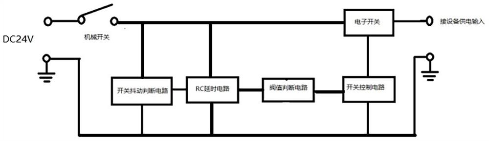
[0041] refer to figure 1 , In the embodiment of the present application, an anti-sparking circuit is provided, and the anti-sparking circuit includes: a switch jitter judgment circuit, an RC delay circuit, a threshold judgment circuit, a switch control circuit and an electronic switch;

[0042] The positive terminal of the power supply is electrically connected to the first terminal of the switch jitter judgment circuit, the first terminal of the RC delay circuit and the first terminal of the electronic switch through the mechanical switch of the device;

[0043] The ...


PUM


Abstract

This application discloses an anti-sparking circuit and a power supply, wherein the positive end of the power supply is electrically connected to the first end of the mechanical switch of the device, the second end of the mechanical switch is connected to the first end of the switch vibration judgment circuit and the RC extension The first end of the timing circuit is electrically connected to the first end of the electronic switch; the second end of the RC delay circuit is electrically connected to the second end of the switch jitter judgment circuit, and the third end of the RC delay circuit is connected to the threshold judgment circuit. The first end of the circuit is electrically connected; the first end of the switch control circuit is electrically connected to the second end of the threshold judgment circuit, and the second end of the switch control circuit is electrically connected to the second end of the electronic switch; the electronic switch The third terminal is electrically connected to the positive pole of the equipment power supply circuit; the negative pole of the power supply is connected to the third terminal of the switch jitter judgment circuit, the fourth terminal of the RC delay circuit, the third terminal of the switch control circuit and the negative pole of the equipment power supply circuit sexual connection. Thereby avoiding the impact of instantaneous high current, and will not produce sparking phenomenon.

Description

technical field [0001] The present application relates to the technical field of power supply, and in particular, to a fire prevention circuit and a power supply. Background technique [0002] Existing DC high-current power supply products, when the mechanical switch is closed or the power supply is unplugged, a large current flows instantaneously, and a spark phenomenon often occurs. On the one hand, this phenomenon will cause oxidation at the switch or power supply interface. It will cause damage to the switch or power interface, and on the other hand, sparks will be generated in the ignition phenomenon, resulting in a fire hazard. SUMMARY OF THE INVENTION [0003] The main purpose of this application is to provide an anti-sparking circuit and a power supply, aiming to solve the problem of the existing DC high-current power supply products, when the mechanical switch is closed or the power supply is unplugged and plugged, there is an instantaneous large current flowing, ...

Claims


Application Information

Patent Timeline
Patent Type & Authority Patents(China)
IPC IPC(8): H02H3/087
Inventor 王洪勇宋庆易永忠
Owner 万灵帮桥医疗器械(广州)有限责任公司
Why Eureka
Try Eureka