
Laser radar calibration equipment

A technology of laser radar and calibration equipment, which is applied in the direction of radio wave measurement systems and instruments, can solve the problems of low efficiency of laser radar calibration methods, and achieve the effect of simple structure, convenient operation and high calibration efficiency

Pending Publication Date: 2022-04-05
武汉天眸光电科技有限公司
View PDF0 Cites 0 Cited by
  • Summary
  • Abstract
  • Description
  • Claims
  • Application Information

AI Technical Summary

Problems solved by technology

[0003] The main purpose of the present invention is to propose a laser radar calibration device, aiming to solve the problem of low efficiency of the current laser radar calibration method

Method used


Image

  • Laser radar calibration equipment
  • Laser radar calibration equipment
  • Laser radar calibration equipment

Examples


Embodiment Construction

[0034] The following will clearly and completely describe the technical solutions in the embodiments of the present invention with reference to the accompanying drawings in the embodiments of the present invention. Obviously, the described embodiments are only part of the embodiments of the present invention, not all of them. Based on the embodiments of the present invention, all other embodiments obtained by persons of ordinary skill in the art without creative efforts fall within the protection scope of the present invention.

[0035] It should be noted that if there are directional indications involved in the embodiment of the present invention, the directional indications are only used to explain the relative positional relationship, movement conditions, etc. between the components in a specific posture. If the specific posture changes , then the directional indication changes accordingly.

[0036] In addition, if there are descriptions involving "first", "second" and so o...


PUM


Abstract

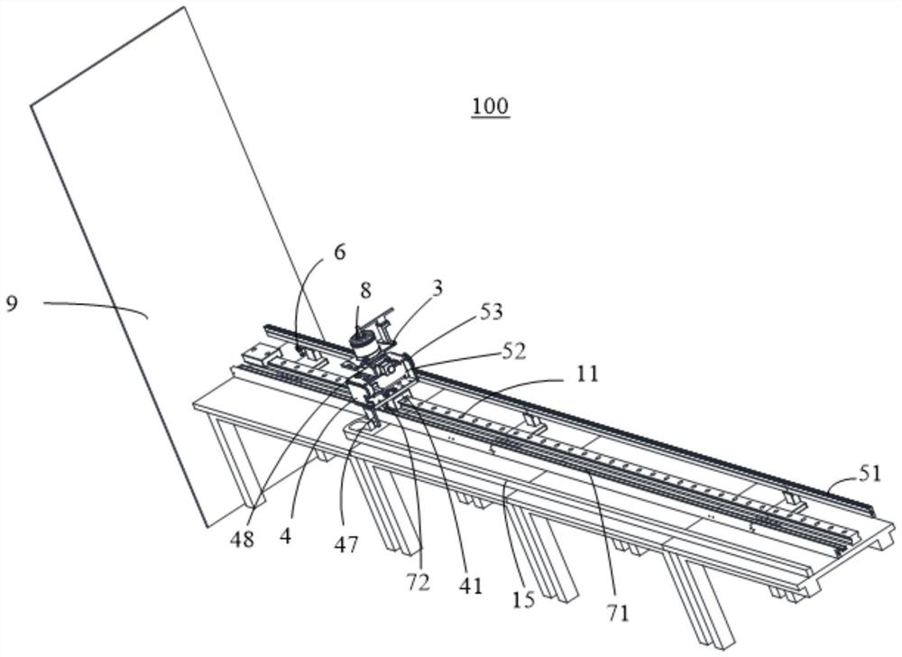
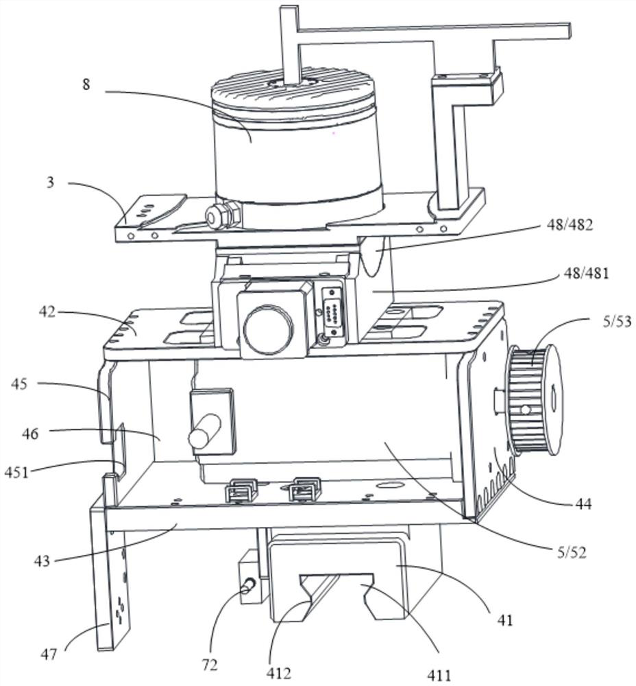
The invention discloses laser radar calibration equipment, which comprises a calibration platform, a fixed seat, a movable seat and a driving mechanism, and is characterized in that the fixed seat is fixedly mounted on the calibration platform, the movable seat is movably mounted on the calibration platform, the movable seat has a moving stroke close to and far away from the fixed seat, and the driving mechanism is mounted on the fixed seat. One of the fixed seat and the movable seat is used for installing a laser radar, and the other one is used for installing a detection object; and the driving mechanism drives the movable seat to move for the stroke so as to adjust the detection distance between the laser radar and the detection object. The structure is simple, operation is convenient, and calibration precision is high.

Description

technical field [0001] The invention relates to the technical field of laser radar, in particular to a laser radar calibration device. Background technique [0002] Before the laser radar is installed, it needs to be calibrated to ensure the pass rate. The existing laser calibration method has a complicated structure, and it is necessary to manually adjust the distance between the laser radar and the detection object, which is time-consuming, laborious and inefficient. Contents of the invention [0003] The main purpose of the present invention is to propose a laser radar calibration device, aiming at solving the problem of low efficiency of the current laser radar calibration method. [0004] In order to achieve the above object, the present invention proposes a laser radar calibration device, including: [0005] calibration platform; [0006] A fixed seat and a movable seat, the fixed seat is fixedly installed on the calibration platform, the movable seat is movably in...

Claims


Application Information

Patent Timeline
Patent Type & Authority Applications(China)
IPC IPC(8): G01S7/497
Inventor 程刚王爽赵胜强徐文东官超
Owner 武汉天眸光电科技有限公司
Learn More