

Intelligent parking management system
A parking management and parking lot management technology, applied in the field of intelligent parking, can solve problems such as traffic accidents, road narrowing, and road space occupation, and achieve the effect of ensuring smooth network
- Summary
- Abstract
- Description
- Claims
- Application Information
AI Technical Summary
Problems solved by technology
Method used
Image

Examples
Embodiment 1
[0032] Example 1, such as Figure 1-9 As shown, an intelligent parking management system is provided, including: a main control module, a radio frequency card reader circuit, a power supply circuit, a motor drive circuit, a LORA wireless circuit, a display circuit, a parking space circuit, a peripheral circuit, and an Ethernet circuit. The control module includes a chip U12, the power supply circuit provides a stable voltage for the entire system, the radio frequency reader circuit records the information of the parked vehicle, the motor drive circuit is responsible for the telescopic conversion of the parking system, and the LORA circuit is responsible for parking on each floor Various information feedback of the system, the display circuit displays information such as the license plate number, remaining parking spaces, parking fees, etc., the peripheral circuit is responsible for executing various instructions conveyed by the main control chip and storing data, and the Ethern...
Embodiment 2
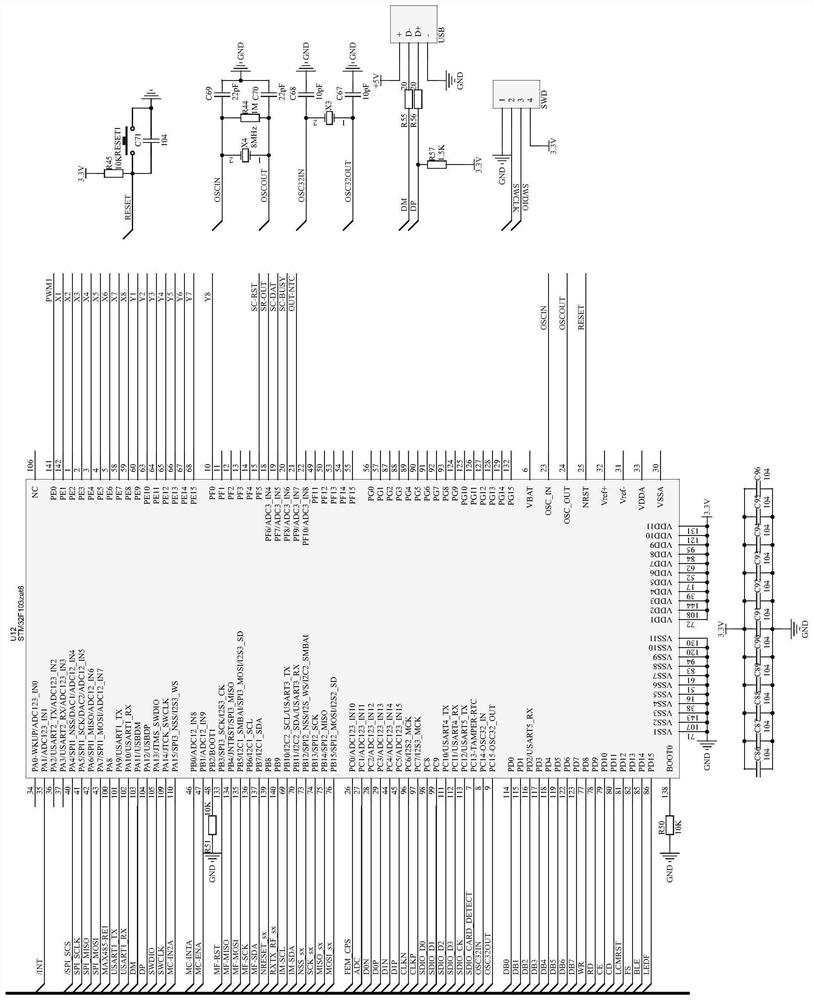
[0033] Example 2, such as figure 1 As shown, the pins 138 and 48 of the chip U12 are respectively grounded through resistors R50 and R51, the pins 71, 107, 143, 38, 16, 51, 61, 83, 94, 120, and 130 are grounded, and the pins 72, 108, 144, 39, 17, 52, 62, 84, 95, 121, 131 are connected to 3.3V power supply, filter capacitors C86-C96 are connected in parallel and set between 3.3V power supply and ground, crystal oscillator X4, resistor R44, capacitor C69, C70 is set between the pins 23 and 24 of the chip U12, the pins 8 and 9 of the chip U12 are respectively grounded through the capacitors C68 and C67, and the crystal oscillator X3 is set between the pins 8 and 9 of the chip U12 , the pins 103 and 104 of the chip U12 are respectively connected to the USB interface through resistors R55 and R56, the first lead of the pin 25 is connected to a 3.3V power supply through a resistor R45, the second lead is grounded through a capacitor C71, and the switch is set at the The two ends of...
Embodiment 3
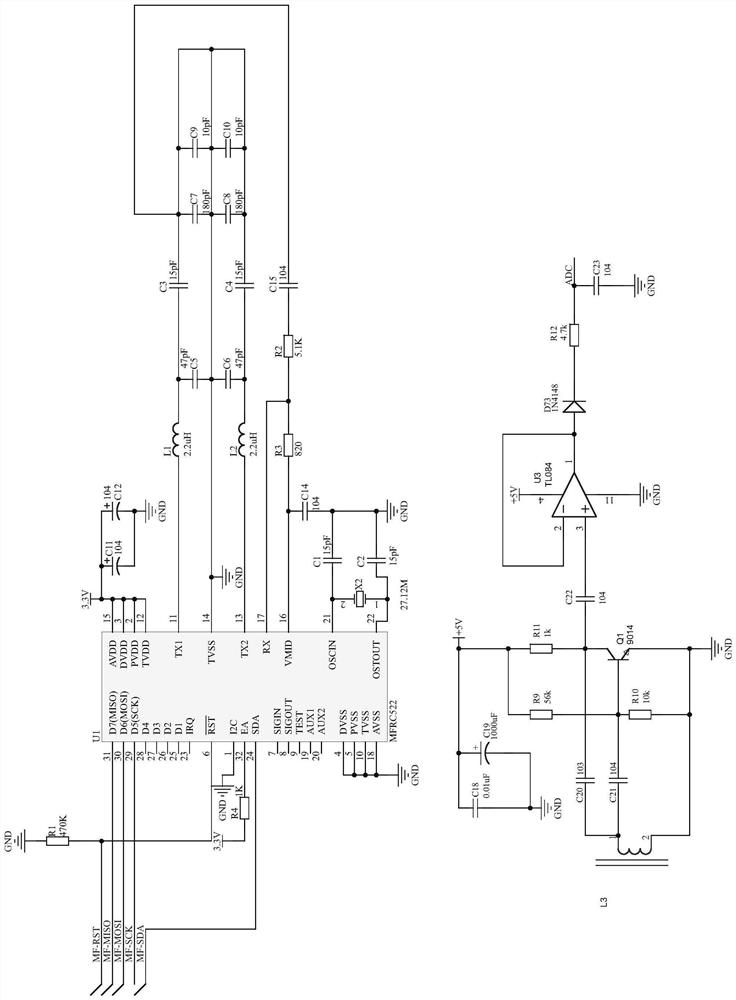
[0035] Example 3, such as figure 2 As shown, the radio frequency reading card circuit includes chips U1, U3, the pins 1, 4, 5, 10, 14, 18 of the chip U1 are grounded, the pin 6 is grounded through the resistor R1, and the pin 32 is grounded through the resistor R1 , pins 2, 3, 12, 15 are connected to 3.3V power supply, capacitors C11 and C12 are connected in parallel and set between 3.3V power supply and ground, and pins 11 and 13 are respectively connected to the above described The pin 14 of the chip U1, the capacitors C5, C7 and C9 are connected in parallel and set between the pins 11 and 13 of the chip U1, and the capacitors C6, C8 and C10 are connected in parallel and set between the pins 13 and 14 of the chip U1 Between, the pin 17 of the chip U1 is connected to the pin 14 of the chip U1 through the resistor R2 and the capacitor C15, and the first lead of the pin 16 of the chip U1 is connected to the said chip U1 through the resistor R2, R3 and the capacitor C15. The p...
PUM
 Abstract
Description
Claims
Application Information