Power factor correction circuit, control system and power supply equipment

A power factor correction and control system technology, applied in the direction of high-efficiency power electronic conversion, output power conversion devices, electrical components, etc., can solve the problems of radiation and electromagnetic interference, high cost of power supply equipment, large inductance and other problems, and prolong life. , The effect of reducing the average current stress and improving the working efficiency

Pending Publication Date: 2022-04-05
GREE ELECTRIC APPLIANCES INC
View PDF0 Cites 0 Cited by
  • Summary
  • Abstract
  • Description
  • Claims
  • Application Information

AI Technical Summary

Problems solved by technology

[0003] In order to overcome at least to a certain extent the problems of excessive current stress and voltage stress on the switching device of the single-stage power factor correction circuit, which are easily damaged and will cause serious radiation and electromagnetic interference, as well as the large inductor volume and high cost of power supply equipment , the application provides a power factor correction circuit, control system and power supply equipment

Method used


Image

  • Power factor correction circuit, control system and power supply equipment
  • Power factor correction circuit, control system and power supply equipment
  • Power factor correction circuit, control system and power supply equipment

Examples


Embodiment Construction

[0031] In order to make the purpose, technical solution and advantages of the present application clearer, the technical solution of the present application will be described in detail below. Apparently, the described embodiments are only some of the embodiments of this application, not all of them. Based on the embodiments in the present application, all other implementation manners obtained by persons of ordinary skill in the art without creative efforts fall within the protection scope of the present application.

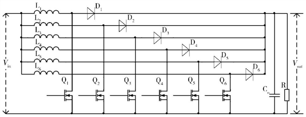
[0032] figure 1 A circuit diagram of a power factor correction circuit provided for an embodiment of the present application, such as figure 1 As shown, the power factor correction circuit includes:

[0033] Input busbar, at least two parallel-connected power factor correction branches connected to the input busbar, and filter capacitor C connected in parallel at both ends of the input busbar o and load R;

[0034] Each power factor correction branch includes...


PUM


Abstract

The invention relates to a power factor correction circuit, a control system and power supply equipment, and the power factor correction circuit comprises an input bus, at least two power factor correction branches which are connected with the input bus in parallel, and a filter capacitor and a load which are connected with the two ends of the input bus in parallel, each power factor correction branch comprises an energy storage inductor, and a switch tube and a diode which are connected with the energy storage inductor, and the switch tube and the diode are respectively connected with a filter capacitor and a load; the input bus is connected with an input power supply. According to the invention, the capacity of a single energy storage inductor can be reduced, the average current stress and output current ripples of a switching device can be reduced, the service life of the switching device is prolonged, the cost of power equipment is reduced, and the working efficiency of the power equipment is improved.

Description

technical field [0001] The application belongs to the technical field of power supply circuits, and in particular relates to a power factor correction circuit, a control system and power supply equipment. Background technique [0002] Power Factor Correction (PFC) refers to the relationship between active power and total power, that is, the ratio of active power to total power. The power factor can measure the degree to which electricity is effectively utilized. The larger the power factor value, the higher the power utilization rate. Power factor correction circuits are widely used in high-power AC-to-DC power supplies. With the continuous development of electric vehicles and backup energy storage battery stations, the power required for AC power supply equipment is also increasing, and the use of traditional single-stage power factor correction circuit structures is limited. When the power increases, the switching devices of the single-stage power factor correction circu...

Claims


Application Information

Patent Timeline
Patent Type & Authority Applications(China)
IPC IPC(8): H02M1/42H02M1/44H02M1/32
CPCY02B70/10
Inventor 程义李伟进陈金奇张家力
Owner GREE ELECTRIC APPLIANCES INC
Why Eureka
Try Eureka