Buffer type overflow valve structure

A relief valve and valve body technology, applied in the field of hydraulic relief valves, can solve problems such as poor buffering effect, achieve sufficient buffering time, obvious effect, and improve service life

Active Publication Date: 2022-04-08
江苏二马液压元件有限公司
View PDF11 Cites 1 Cited by
  • Summary
  • Abstract
  • Description
  • Claims
  • Application Information

AI Technical Summary

Problems solved by technology

[0004]The purpose of the present invention is to solve the problem of poor buffering effect in the prior art, and the proposed buffer relief valve structure

Method used


Image

  • Buffer type overflow valve structure
  • Buffer type overflow valve structure
  • Buffer type overflow valve structure

Examples


Embodiment

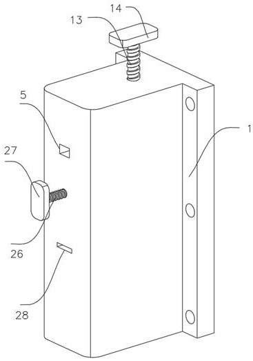
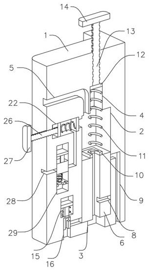
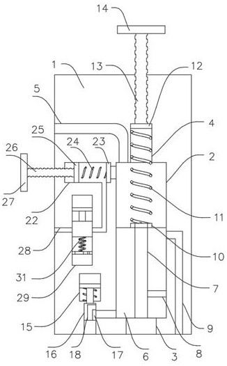
[0023] refer to Figure 1-6 , buffer relief valve structure, including a valve body 1, a valve chamber 2 is opened inside the valve body 1, an oil inlet 3 and an oil outlet 5 are opened through the side wall of the valve chamber 2, and an oil inlet 3 and an oil outlet 5 are opened on the inner wall of the valve chamber 2. The adjustment groove 4, the inner wall of the valve cavity 2 is sealed and slidingly connected with the valve core 6, the oil inlet 3 and the oil outlet 5 are located at both ends of the valve core 6, and the oil outlet 5 can be blocked and closed when the valve core 6 moves to the limit position The side wall of the valve core 6 is provided with an oil return hole 7, the side wall of the oil passage 7 is provided with an oil return hole 8, and the inner wall of the valve cavity 2 is provided with an oil return port 9 matching the oil return hole 8, The end of the spool 6 is fixed with a connecting block 10, and the connecting block 10 is connected with a sl...


PUM


Abstract

The buffer type overflow valve structure comprises a valve body, a valve cavity is formed in the valve body, an oil inlet and an oil outlet are formed in the side wall of the valve cavity in a penetrating mode, an adjusting groove is formed in the inner wall of the valve cavity, a valve element is connected to the inner wall of the valve cavity in a sealed and sliding mode, and an oil through hole is formed in the side wall of the valve element in a penetrating mode. An oil passing hole is formed in the valve cavity, an oil return hole is formed in the side wall of the oil passing hole, an oil return opening matched with the oil return hole is formed in the inner wall of the valve cavity in a penetrating mode, a connecting block is fixed to the end of the valve element and connected with a sliding block through a main pressure spring, the sliding block is in sealed sliding connection with the inner wall of the adjusting groove, and a main adjusting screw rod is fixed to the end of the sliding block. The device has the advantages that when the oil pressure is high and is still greatly increased, the oil pressure entering the oil outlet can be reduced, so that the oil pressure in the device is increased and reduced, the oil pressure is buffered, and damage caused by great increase under the high pressure is avoided.

Description

technical field [0001] The invention relates to the technical field of hydraulic relief valves, in particular to a buffer relief valve structure. Background technique [0002] The relief valve plays the role of safety protection in the hydraulic system. When the system pressure exceeds the specified value, the safety valve will be opened to discharge a part of the oil in the system into the oil tank, so that the system pressure does not exceed the allowable value, so as to ensure that the system will not be affected by pressure. Accidents due to excessive height; [0003] When the existing relief valve is applied to hydraulic equipment, when the load of the equipment increases instantaneously and the oil pressure increases too fast, the spool of the relief valve will be subjected to excessive impact, and the pressure unloading will be completed through its own movement, and the moment the pressure increases, The rapid movement of the spool will lead to increased wear, and t...

Claims


Application Information

Patent Timeline
Patent Type & Authority Applications(China)
IPC IPC(8): F15B13/02F15B20/00
Inventor 冯森蕾
Owner 江苏二马液压元件有限公司
Why Eureka
Try Eureka