Computer fine-tuning type electrically-controlled rotary camera

A rotating camera and electric control technology, which is applied to color TV parts, TV system parts, TVs, etc., can solve the problems of not having multi-angle adjustment functions, excessively large adjustment angles, and inconvenient installation efficiency. , to achieve the effect of easy installation, operation and handling, simple installation and simple structure

Inactive Publication Date: 2022-04-08
杭州很美网络科技有限公司
View PDF0 Cites 0 Cited by
  • Summary
  • Abstract
  • Description
  • Claims
  • Application Information

AI Technical Summary

Problems solved by technology

[0004] The purpose of the present invention is to provide a computer fine-tuning type electric control rotating camera to solve the above-mentioned problems in the background technology that more steps need to be performed when the current camera is installed, and more people are required to cooperate with the installation. work, which caused some inconvenience and had a certain impact on the efficiency of installation. At the same time, the direct rotation of the motor was used to adjust the angle, which would cause the adjustment angle to be too large, and it did not have multiple angles when adjusting. The adjustment function makes it have a certain impact on the later use

Method used


Image

  • Computer fine-tuning type electrically-controlled rotary camera
  • Computer fine-tuning type electrically-controlled rotary camera
  • Computer fine-tuning type electrically-controlled rotary camera

Examples


Embodiment Construction

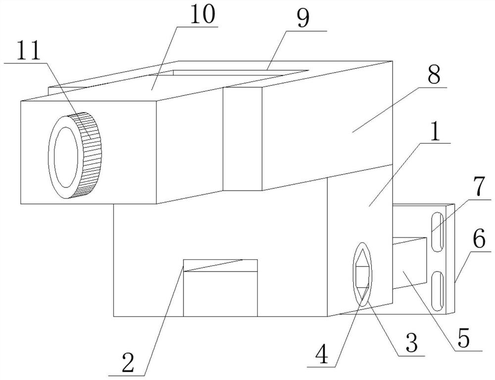
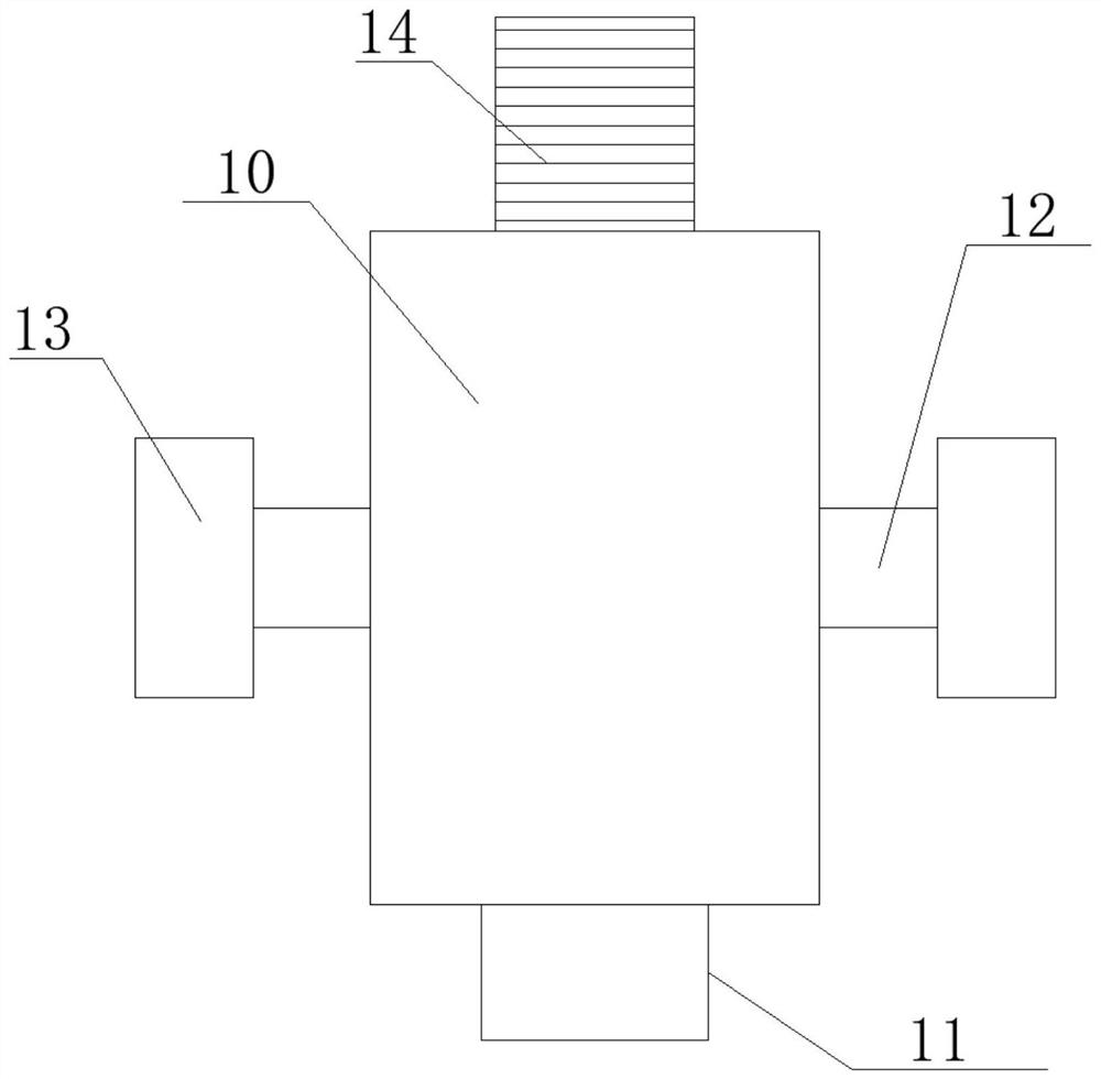
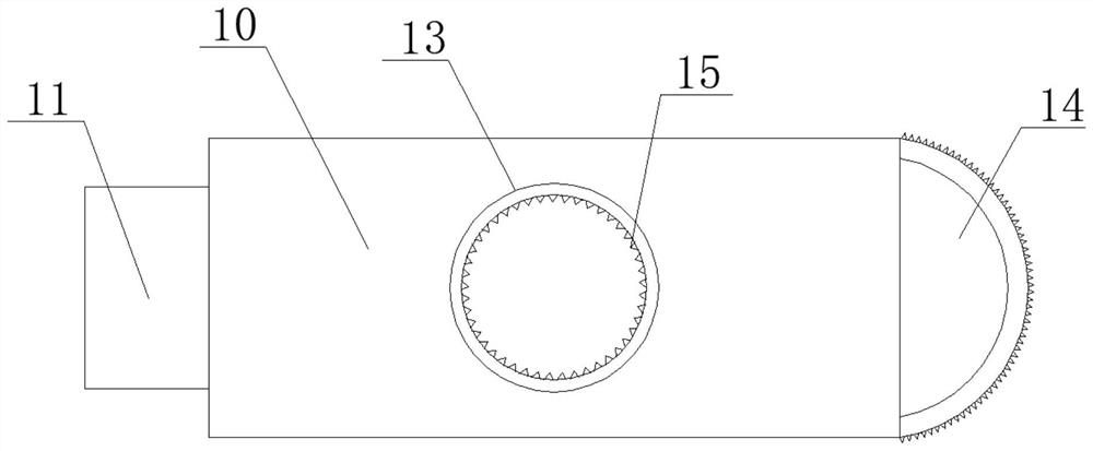
[0028] see Figure 1-3 , in an embodiment of the present invention, a computer fine-tuning electric control rotary camera includes a bottom support block 1, the bottom surface of the bottom support block 1 is horizontally provided with a bottom turning groove 2, and one side of the bottom support block 1 is horizontally provided with a fixed The screw hole 3, the inner side of the fixed screw hole 3 is horizontally inserted with the adjusting screw 4, the bottom turning groove 2 is set horizontally at the center of the bottom surface of the bottom support block 1, and both sides of the bottom turning groove 2 run through the bottom support block The two sides of 1 extend to the outside, and the fixed screw hole 3 is horizontally opened on the side of the bottom support block 1 close to the bottom surface, and the inside of the fixed screw hole 3 is kept connected with the inside of the bottom turning groove 2, and the adjustment screw 4 One end extends through the fixed screw ...


PUM


Abstract

The invention discloses a computer fine tuning type electric control rotary camera, and relates to the field of cameras, the computer fine tuning type electric control rotary camera comprises a bottom support block, the bottom surface of the bottom support block is horizontally provided with a bottom overturning groove, one side edge of the bottom support block is horizontally provided with a fixing screw hole, and the inner side edge of the fixing screw hole is horizontally inserted with an adjusting screw rod; a supporting transverse rod is in butt joint with one side edge of the bottom supporting block, a fixing side plate is welded to the end, away from the bottom supporting block, of the supporting transverse rod, a connecting through hole is formed in the side edge of the fixing side plate, and a horizontal top block is in horizontal butt joint with the top face of the bottom supporting block. A clamping turning groove is horizontally formed in the side edge, away from the bottom supporting block, of the horizontal top block, and a main camera is arranged on the inner side edge of the clamping turning groove. The device is designed to be split, the structure is simple, installation is more convenient and faster by adopting a clamping mode, and multi-angle fine adjustment treatment can be met by adopting multi-direction adjustment.

Description

technical field [0001] The invention relates to the technical field of cabinet installation components, in particular to a computer fine-tuning electric control rotating camera. Background technique [0002] Cameras can be divided into two categories: digital cameras and analog cameras. A digital camera can convert the analog video signal generated by the video capture device into a digital signal, and then store it in the computer. The video signal captured by the analog camera must be converted to a digital mode by a specific video capture card and compressed before it can be converted to a computer for use. Digital camera can directly capture image, then passes in the computer by string, parallel port or USB interface. The cameras on the computer market are basically digital cameras, and among the digital cameras are USB digital cameras using new data transmission interfaces. Most of the products seen on the market are such products. [0003] For the current cameras, m...

Claims


Application Information

Patent Timeline
Patent Type & Authority Applications(China)
IPC IPC(8): F16M13/02F16M11/10F16M11/08F16M11/18H04N5/225
Inventor 王德刚
Owner 杭州很美网络科技有限公司
Why Eureka
Try Eureka