Electrical integrated power distribution cabinet
A power distribution cabinet and electrical technology, applied in substation/distribution device casing, electrical components, substation/switch layout details, etc., can solve problems such as increased capital expenditure, reduced work efficiency, and small wiring space, to avoid obstruction and distracting, easy-to-see effects
- Summary
- Abstract
- Description
- Claims
- Application Information
AI Technical Summary
Problems solved by technology
Method used
Image
Examples
Embodiment 1
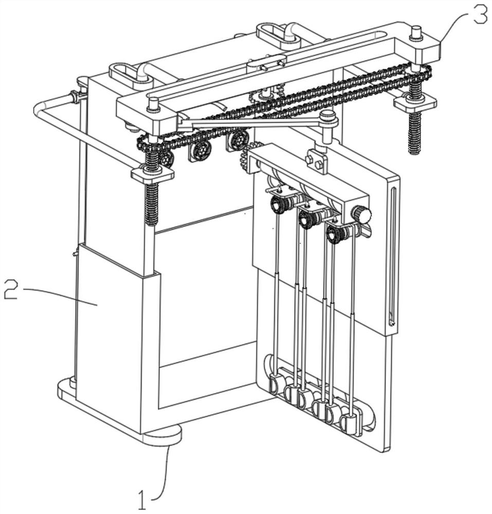
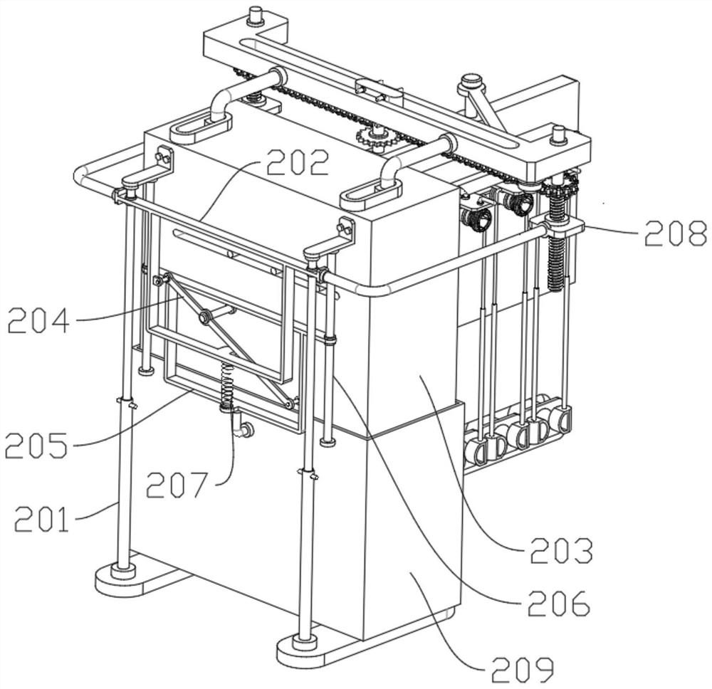
[0035] Please refer to Figure 2 to Figure 4 As shown, an electrical integrated power distribution cabinet includes a base 1, a folding adjustment mechanism 2 is arranged on the upper end of the base 1, and a removal mechanism 3 is arranged on the upper end of the folding adjustment mechanism 2, and the folding adjustment mechanism 2 includes a double-section sliding rod 201, a first frame 202, inner casing 203, lifting rod 204, second frame 205, positioning rod 206, the outer surface of the upper end of the double-section sliding rod 201 is slidingly connected with the first frame 202, and the upper end of the double-section sliding rod 201 is fixedly connected with the inner casing 203, the second The left end of a frame 202 is rotatably connected to the lifting rod 204, the left end of the lifting rod 204 is rotatably connected to the front end of the inner shell 203, the right end of the lifting rod 204 is rotatably connected to the right end of the second frame 205, and th...
Embodiment 2
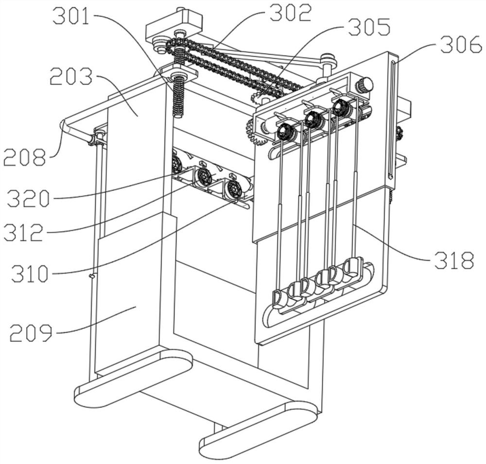
[0039] Please refer to figure 2 and Figures 4 to 10 As shown, the removal mechanism 3 comprises a sprocket threaded rod 301, a chain 302, a curved chute plate 303, a slide block 304, a power sprocket 305, a double-section plate 306, a push rod 307, a straight groove 308, and the inner threaded rod 208 right-hand thread A sprocket threaded rod 301 is connected, and one end of the sprocket threaded rod 301 is connected to a chain 302 through transmission. The lower end of the groove 308 is fixedly connected to the upper surface of the inner shell 203, the middle end of the curved chute plate 303 is slidably connected with a slider 304, and the lower end of the slider 304 is rotatably connected with a power sprocket 305, and the lower end of the power sprocket 305 is engaged with one end of the chain 302, and the power The lower end of the sprocket 305 is fixedly connected with a double-section plate 306, the middle end of the double-section plate 306 is rotatably connected wi...
Embodiment 3
[0046] Please refer to Figure 1 to Figure 10As shown, an electrical integrated power distribution cabinet includes a base 1, a folding adjustment mechanism 2 is arranged on the upper end of the base 1, and a removal mechanism 3 is arranged on the upper end of the folding adjustment mechanism 2, and the folding adjustment mechanism 2 includes a double-section sliding rod 201, a first frame 202, inner casing 203, lifting rod 204, second frame 205, positioning rod 206, the outer surface of the upper end of the double-section sliding rod 201 is slidingly connected with the first frame 202, and the upper end of the double-section sliding rod 201 is fixedly connected with the inner casing 203, the second The left end of a frame 202 is rotatably connected to the lifting rod 204, the left end of the lifting rod 204 is rotatably connected to the front end of the inner shell 203, the right end of the lifting rod 204 is rotatably connected to the right end of the second frame 205, and th...
PUM
 Abstract
Description
Claims
Application Information
 - R&D
- Intellectual Property
- Life Sciences
- Materials
- Tech Scout
- Unparalleled Data Quality
- Higher Quality Content
- 60% Fewer Hallucinations
Browse by: Latest US Patents, China's latest patents, Technical Efficacy Thesaurus, Application Domain, Technology Topic, Popular Technical Reports.
© 2025 PatSnap. All rights reserved.Legal|Privacy policy|Modern Slavery Act Transparency Statement|Sitemap|About US| Contact US: help@patsnap.com


