Rubber forming equipment for petroleum product processing

A technology for rubber molding and petroleum products, applied in cleaning methods and utensils, cleaning methods using tools, chemical instruments and methods, etc., can solve the problems of large manpower consumption and low molding efficiency

Pending Publication Date: 2022-04-12
深圳市争先科技有限公司
View PDF0 Cites 0 Cited by
  • Summary
  • Abstract
  • Description
  • Claims
  • Application Information

AI Technical Summary

Problems solved by technology

[0004] In order to overcome the shortcomings of manual operation that consumes a lot of manpower and low molding efficiency, the technical problem of the present invention is to provide a rubber molding equipment for petroleum product processing that can save manpower and improve molding efficiency

Method used


Image

  • Rubber forming equipment for petroleum product processing
  • Rubber forming equipment for petroleum product processing
  • Rubber forming equipment for petroleum product processing

Examples


Embodiment 1

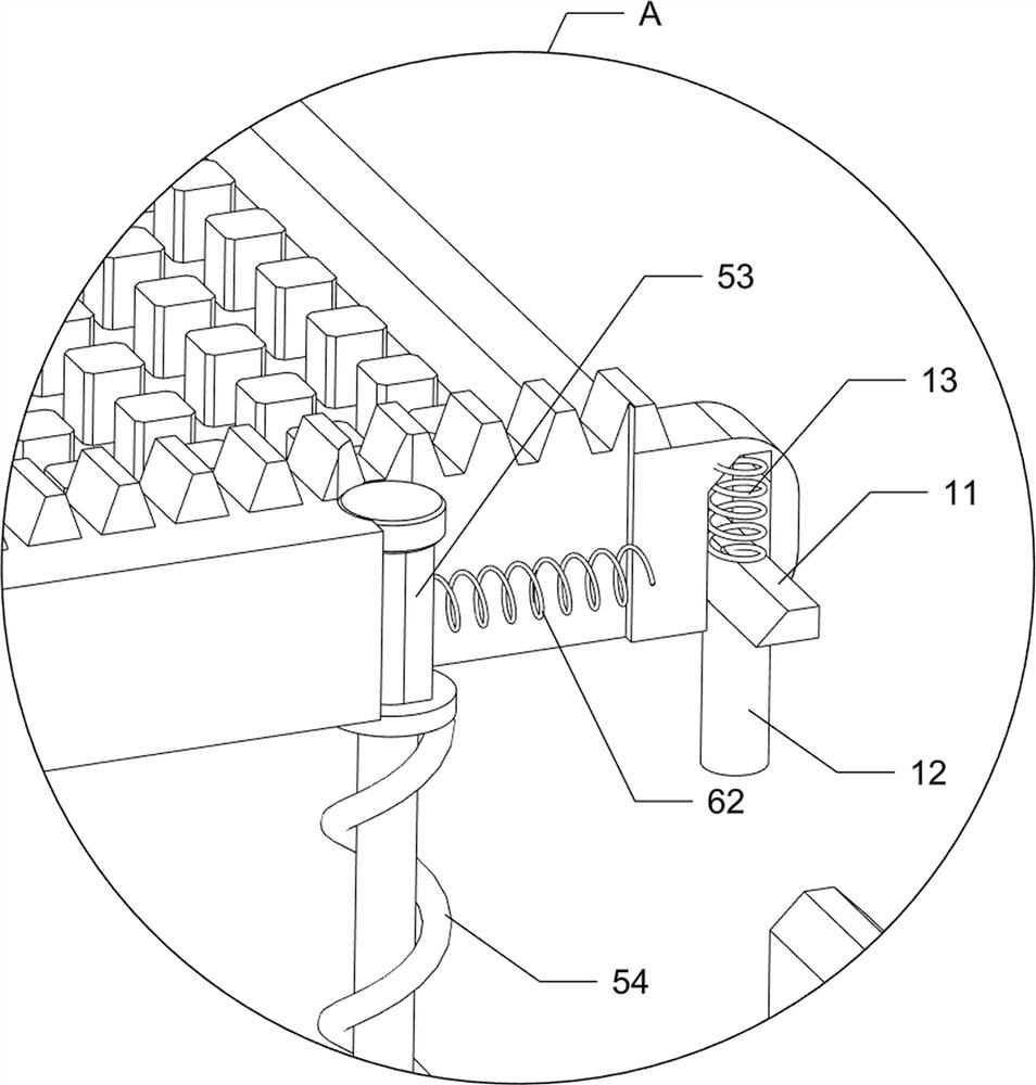
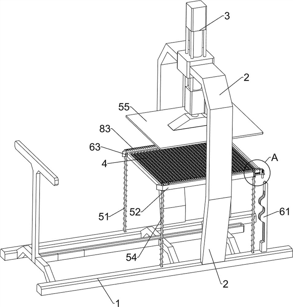
[0076] A kind of rubber molding equipment for petroleum product processing, such as Figure 1-3As shown, it includes a frame 1, a support frame 2, a first cylinder 3, a forming film tool 4, a compacting assembly 5 and a shaking mechanism 6, the front side of the frame 1 is provided with a support frame 2, and the upper part of the support frame 2 is provided with a second A cylinder 3, a compaction assembly 5 is connected between the frame 1 and the first cylinder 3, and a molding film 4 is placed on the compaction assembly 5 in a sliding manner, and a shaking is provided between the compaction assembly 5 and the frame 1. Institution 6.

[0077] The compaction assembly 5 includes a first connecting rod 51, a slide rod 52, a sliding sleeve 53, a first spring 54 and a pressing plate 55. The left and right sides of the frame 1 are symmetrically provided with the first connecting rod 51, and the first connecting rod 51 top Sliding sleeves 53 are all slidably connected, and slidin...

Embodiment 2

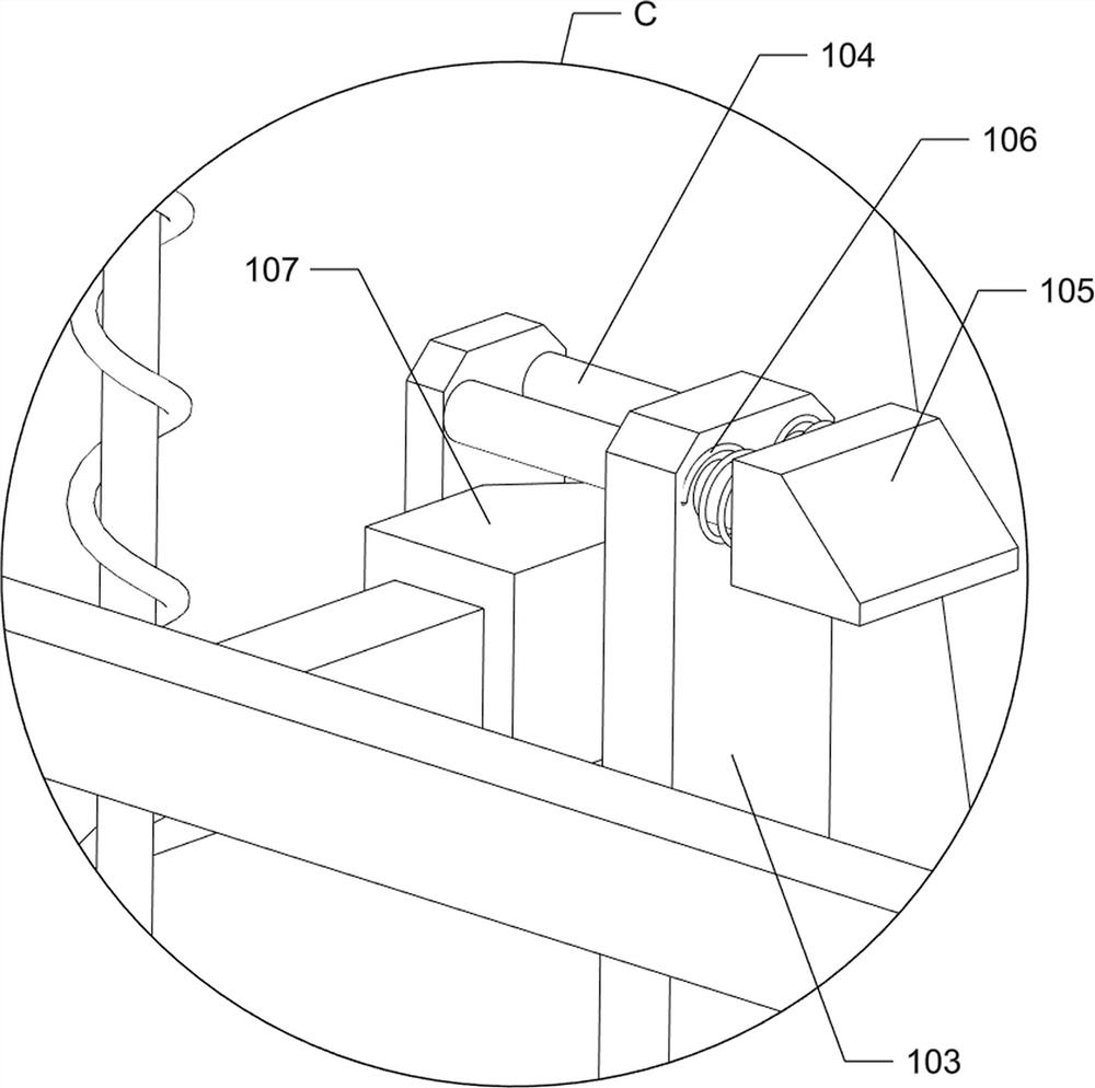
[0081] On the basis of Example 1, such as Figure 2-8 As shown, it also includes a blanking assembly 7, and the blanking assembly 7 includes a first support rod 71, a second cylinder 72, a blanking frame 73, a baffle 74, a second connecting rod 75, an L-shaped guide rod 76, a first Three connecting rods 77, the third spring 78, the fourth connecting rod 79, the toggle lever 710, the fourth spring 711 and the fifth connecting rod 712, the rear side of the frame 1 is symmetrically provided with the first support rod 71, the first support Bar 71 tops are all provided with the second cylinder 72, and the blanking frame 73 is connected between the front sides of the second cylinder 72 telescopic rods, and the lower side of the blanking frame 73 is slidably connected with the baffle plate 74, and the left and right symmetrical design of the baffle plate 74 rear side. There is a second connecting rod 75, and the left and right sides of the blanking frame 73 are symmetrically provided...


PUM


Abstract

The invention relates to forming equipment, in particular to rubber forming equipment for petroleum product processing. The rubber forming equipment for petroleum product processing aims at achieving the technical effects that manpower can be saved, and the forming efficiency can be improved. Rubber forming equipment for petroleum product processing comprises a rack and a supporting frame, and the supporting frame is arranged on one side of the rack; the first air cylinder is arranged on the supporting frame; the compaction assembly is connected between the rack and the first air cylinder; the molding die is arranged on the compaction assembly part in a sliding manner; and the shaking mechanism is arranged between the compaction assembly part and the rack. Through cooperation between the discharging assembly and the self-starting switch assembly, the first air cylinder can be automatically started.

Description

technical field [0001] The invention relates to a molding device, in particular to a rubber molding device for processing petroleum products. Background technique [0002] As we all know, most of the rubber parts are manufactured through mold processing. People usually fill the corresponding mold with melted rubber raw materials to make rubber parts with specific shapes. This kind of processing mold is easy to use and easy to operate, and can obtain High-quality rubber parts are widely used. The existing rubber processing technology requires manual operation, which consumes a lot of manpower. Manually processing rubber to shape the rubber will easily affect the molding efficiency of the rubber. [0003] Therefore, it is necessary to develop a rubber molding equipment for petroleum product processing that can save manpower and improve molding efficiency. Contents of the invention [0004] In order to overcome the shortcomings of manual operation that consumes a lot of manp...

Claims


Application Information

Patent Timeline
IPC IPC(8): B29C43/32B29C43/34B29C43/50B29C33/72B08B1/02
Inventor 李强
Owner 深圳市争先科技有限公司
Why Eureka
Try Eureka