Locking mechanism

A locking mechanism and connecting rod technology, applied in structural parts, electric vehicles, electrical components, etc., can solve the problems of poor compatibility of the height error of the pressing force direction, small driving force amplification effect, and small driving force amplification ratio. Achieve the effect of small space path requirements, improved stability, and compact locking mechanism

Pending Publication Date: 2022-04-12
苏州睿锂物联科技有限公司
View PDF0 Cites 0 Cited by
  • Summary
  • Abstract
  • Description
  • Claims
  • Application Information

AI Technical Summary

Problems solved by technology

Among them, the claw-type locking mechanism can amplify the thrust of the driving device by adjusting the transmission ratio through the lever, but due to structural constraints, the amplification ratio of the driving force is generally 1 to 2 times, and the pressing device converts the thrust into a downward force through an inclined surface. The transmission ratio of some structures is a constant value, and the compatibility with height errors in the direction of the pressing force is poor
The locking mechanism in the form of a latch adopts a wedge-shaped locking pin to lock. It also converts the thrust into a downward force through an inclined surface. The angle of the inclined surface is close to that of the claw. It also has the problem of poor compatibility with height errors. In order to improve the compatibility with height errors, The inclination of the slope cannot be too small, so the amplification effect on the driving force is also small
[0004] In order to solve the above problems, it is urgent to provide a locking mechanism to solve the problem of a small amplification ratio of the driving force or a large space occupation

Method used


Image

  • Locking mechanism
  • Locking mechanism
  • Locking mechanism

Examples


Embodiment 1

[0041] With the development of new energy technology, the application of new energy batteries is becoming more and more extensive. However, the existing new energy batteries are faced with the problems of short cruising range and slow charging, so a battery replacement technology is proposed to solve the above problems through fast battery replacement. In order to improve the efficiency of battery replacement and maintain the stability of the battery pack, a locking mechanism is generally provided between the battery pack and the vehicle frame to fix the battery pack.

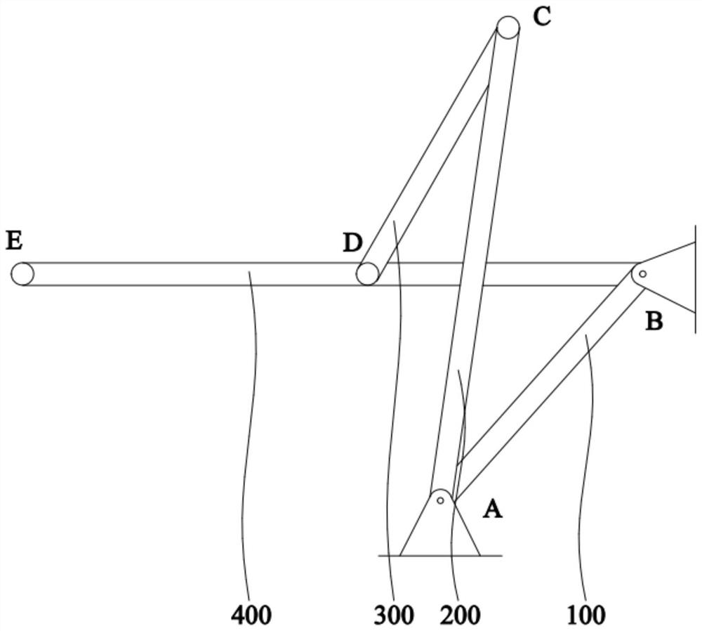
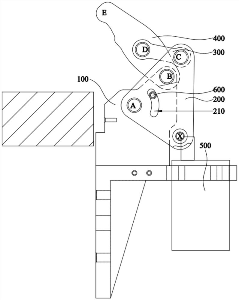
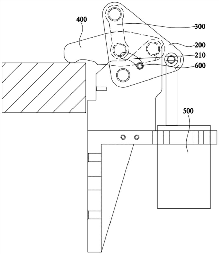
[0042] like figure 1 and figure 2 As shown, the present embodiment provides a locking mechanism, which includes a first link 100 , a second link 200 , a third link 300 , a fourth link 400 and a driving member 500 . The first connecting rod 100 is fixed, the second connecting rod 200 and the first connecting rod 100 are hinged at the pivot point A, the third connecting rod 300 and the second connecting rod 20...


PUM

PropertyMeasurementUnit
Angleaaaaaaaaaa

Abstract

The invention relates to the technical field of electric automobiles, in particular to a locking mechanism. The locking mechanism comprises a first connecting rod, a second connecting rod, a third connecting rod, a fourth connecting rod and a driving piece. The second connecting rod is hinged to the first connecting rod, the third connecting rod is hinged to the second connecting rod, the fourth connecting rod is hinged to the first connecting rod, the fourth connecting rod is hinged to the third connecting rod, and hinge points among the first connecting rod, the second connecting rod, the third connecting rod, the fourth connecting rod and the driving part are different. The third connecting rod and the fourth connecting rod are driven to rotate, so that the free end of the fourth connecting rod presses and fixes the workpiece. According to the structure, the output force of the driving part is amplified through the second connecting rod, the third connecting rod and the fourth connecting rod, the cost of the locking mechanism is reduced, the stability of locking workpieces is improved, meanwhile, the locking mechanism is simple in structure and low in requirement for application space, and the compatibility of the locking mechanism is enhanced.

Description

technical field [0001] The invention relates to the technical field of electric vehicles, in particular to a locking mechanism. Background technique [0002] With the development of new energy technology, the application of new energy batteries is becoming more and more extensive. However, the existing new energy batteries are faced with the problems of short cruising range and slow charging, so a battery replacement technology is proposed to solve the above problems through fast battery replacement. In order to improve the efficiency of battery replacement and maintain the stability of the battery pack, a locking mechanism is generally provided between the battery pack and the vehicle frame to fix the battery pack. [0003] In the prior art, commonly used locking mechanisms include claws, pressing devices and latches. Among them, the claw-type locking mechanism can amplify the thrust of the driving device by adjusting the transmission ratio through the lever, but due to s...

Claims


Application Information

Patent Timeline
IPC IPC(8): B60L53/80B60K1/04H01M50/264H01M50/244H01M50/249
CPCY02E60/10Y02T10/70Y02T10/7072
Inventor 洪木南刘波
Owner 苏州睿锂物联科技有限公司
Why Eureka
Try Eureka