
Mobile camera platform for target tracking

A mobile camera and target tracking technology, which is applied in the field of target tracking mobile camera platform, can solve the problems of large manpower input, movement, inconvenient camera replacement motor, etc., and achieve the effect of easy disassembly and replacement and expanding the scope of use

Inactive Publication Date: 2022-04-12
杨大为
View PDF0 Cites 0 Cited by
  • Summary
  • Abstract
  • Description
  • Claims
  • Application Information

AI Technical Summary

Problems solved by technology

[0002] When large-scale exhibition halls hold exhibition activities, it is necessary to use cameras to take pictures of the bustling scenes in the venue or record some videos as the results of the commemorative exhibition activities. The platforms supported by the bottom of traditional cameras are fixed, and it is not easy to move to different positions with the camera , in order to be able to take photos of multiple different angles of view, it is often necessary to hire multiple photographers to move and shoot at different locations in the venue. It is not possible to move on beams of different thicknesses, which reduces the scope of use of the mobile camera platform. In addition, most mobile camera platforms are not convenient to replace the motor for the camera.

Method used


Image

  • Mobile camera platform for target tracking
  • Mobile camera platform for target tracking
  • Mobile camera platform for target tracking

Examples


Embodiment Construction

[0028] The technical solutions in the embodiments of the present invention will be clearly and completely described below in conjunction with the embodiments of the present invention. Apparently, the described embodiments are only some of the embodiments of the present invention, not all of them. Based on the embodiments of the present invention, all other embodiments obtained by persons of ordinary skill in the art without creative efforts fall within the protection scope of the present invention.

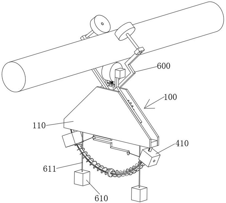
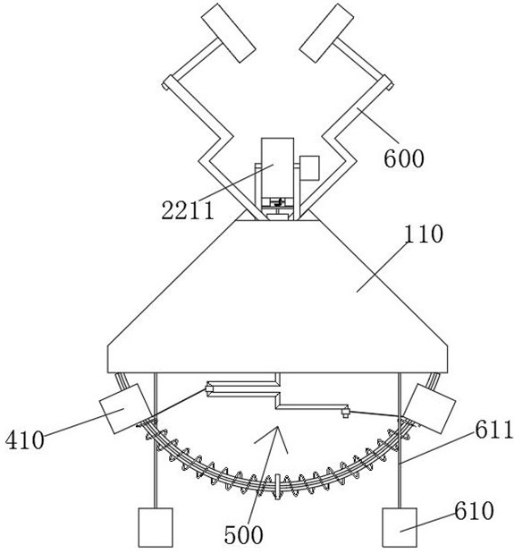
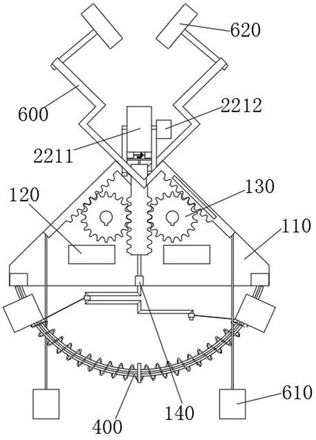
[0029] see Figure 1-9 As shown, a mobile camera platform for target tracking includes a support shell 100, the support shell 100 includes two symmetrically distributed panels 110, two connecting blocks 120 are fixedly connected between the two panels 110, and the two panels 110 There are two symmetrically distributed linkage gears 130 that are rotationally connected between them. A positioning column 200 is provided for meshing transmission between the two linkage gears 130. The ...


PUM


Abstract

The invention relates to the technical field of mobile camera platforms, in particular to a mobile camera platform for target tracking, which comprises a support shell, the support shell comprises two symmetrically distributed panels, two symmetrically distributed linkage gears are rotatably connected between the two panels, a positioning column is in meshing transmission between the two linkage gears, and the positioning column is in meshing transmission with the two panels. A rectangular through hole is formed in the top of the positioning column, a positioning block is slidably connected to the interior of the rectangular through hole, supporting blocks are fixedly connected to the two ends of the positioning block, and a driving roller is rotatably connected between the two supporting blocks. According to the invention, through meshing transmission of a first bevel gear on a first connecting shaft and a second bevel gear on a shaft rod, the shaft rod drives a sleeve to rotate, then the sleeve drives a driving shaft to rotate, and a [-shaped shaft and an L-shaped shaft on the driving shaft can pull a pulling rope between a rotating sleeve and a camera in the rotating process, so that the camera moves along an arc-shaped guide rail; the orientation of the camera lens can be flexibly adjusted, and photos at different angles can be conveniently shot.

Description

technical field [0001] The invention relates to the technical field of mobile camera platforms, in particular to a mobile camera platform for target tracking. Background technique [0002] When large-scale exhibition halls hold exhibition activities, it is necessary to use cameras to take pictures of the bustling scenes in the venue or record some videos as the results of the commemorative exhibition activities. The platforms supported by the bottom of traditional cameras are fixed, and it is not easy to move to different positions with the camera , in order to be able to take photos of multiple different angles of view, it is often necessary to hire multiple photographers to move and shoot at different locations in the venue. It is impossible to move on beams of different thicknesses, which reduces the scope of use of the mobile camera platform. In addition, most mobile camera platforms are not convenient to replace the motor for the camera. Contents of the invention [...

Claims


Application Information

Patent Timeline
Patent Type & Authority Applications(China)
IPC IPC(8): F16M11/04F16M11/10F16M11/18F16M11/42F16M13/02F16M7/00H04N5/225
Inventor 杨大为
Owner 杨大为
Learn More